Contents
PWM is a technique used to generate analog output signal using digital signals. It is commonly used to control average power delivered to a load, motor speed control, generating analog voltage levels and for generating analog waveforms.
CCP Modules are available with a number of PIC Microcontrollers. CCP stands for Capture/Compare/PWM. Using PWM module is far more easier and cost effective than using extra chips for PWM generation. MikroC Pro for PIC Microcontroller provide built-in library for PWM which makes our task very simple.
MikroC Functions
- PWM1_Init(constant long frequency) : This function initializes the PWM module with duty ratio 0. Frequency parameter is the desired frequency in Hz. It should be a numeric constant, should not be a variable.
- PWM1_Set_Duty(unsigned short duty_ratio) : This function is used to set the duty cycle of the PWM. The parameter duty_ratio takes values from 0 to 255, ie 0 means 0% , 127 means 50% and 255 means 100% duty cycle. The PWM1_Init() routine must be called before using this.
- PWM1_Start() : This function starts the PWM output. PWM1_Init() must be called before calling this routine,
- PWM1_Stop() : This function stops the PWM output. PWM1_Init() must be called before calling this routine. PWM1_Start() should be called before calling this function otherwise calling this function will not have any effect as PWM module is not running.
Note 1 : For microcontrollers with more than one CCP module, to use the desired CCP module for PWM generation simply change the number “1” in the prototype with desired module number. eg: PWM2_Init(5000), PWM2_Start().
Note 2 : All PWM modules in a PIC Microcontroller uses Timer 2 for its operation, so you cannot set different frequencies for different PWM modules.
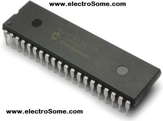
In this tutorial we are using PIC 16F877A for demonstrating PWM generation using CCP module. PIC 16F877A contains two CCP modules.
Circuit Diagram – Using internal PWM Module of PIC
In the below circuit four switches are provided for controlling the Duty Ratio of PWM generated by two CCP modules of the PIC Microcontroller.
- Switch 1 : To increase the Duty Ratio of PWM produced by CCP1
- Switch 2 : To decrease the Duty Ratio of PWM produced by CCP1
- Switch 3 : To increase the Duty Ratio of PWM produced by CCP2
- Switch 4 : To decrease the Duty Ratio of PWM produced by CCP2
The output of the two CCP modules are given to a CRO to observe the changes in pulse width. It may be given to two LEDs and you can see the changes in brightness as Duty Ratio changes.
MikroC Program
void main()
{
  short current_duty_1  = 16; // initial value for current_duty_1
  short current_duty_2 = 16;  // initial value for current_duty_2

  TRISD = 0xFF; // PORTD as input
  TRISC = 0x00; // PORTC as output

  PWM1_Init(5000);  // Initialize PWM1
  PWM2_Init(5000);  // Initialize PWM2

  PWM1_Start();  // start PWM1
  PWM2_Start();  // start PWM2

  PWM1_Set_Duty(current_duty_1); // Set current duty for PWM1
  PWM2_Set_Duty(current_duty_2); // Set current duty for PWM2

  while (1)        // endless loop
  {
     if (!RD0_bit)   // if button on RD0 pressed
     {
      Delay_ms(40);
      current_duty_1++;  // increment current_duty_1
      PWM1_Set_Duty(current_duty_1);  //Change the duty cycle
     }

    if (!RD1_bit)               // button on RD1 pressed
    {
      Delay_ms(40);
      current_duty_1--;  // decrement current_duty_1
      PWM1_Set_Duty(current_duty_1);
     }

    if (!RD2_bit)     // if button on RD2 pressed
    {
      Delay_ms(40);
      current_duty_2++;    // increment current_duty_2
      PWM2_Set_Duty(current_duty_2);
     }

    if (!RD3_bit)       // if button on RD3 pressed
    {
      Delay_ms(40);
      current_duty_2--;   // decrement current_duty_2
      PWM2_Set_Duty(current_duty_2);
     }

    Delay_ms(10);      // slow down change pace a little
  }
}
I thinks the program is self explanatory, so if you have any doubts please comment below…
Download
You can download the MikroC Source Code, Proteus files etc here…
