Interfacing Relay with PIC Microcontroller
Contents
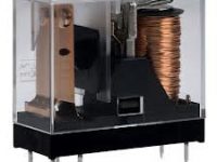
A relay is an electromagnetic switch which is used to switch High Voltage/Current using Low power circuits. Relay isolates low power circuits from high power circuits. It is activated by energizing a coil wounded on a soft iron core. For detailed working of relay please visit this page. A relay should not be directly connected to a microcontroller, it needs a driving circuit.
A relay should not be connected directly to a microcontroller due to following reasons..
- A microcontroller is not able to supply current required for the working of a relay. The maximum current that a PIC Microcontroller can source or sink is 25mA while a relay needs about 50 – 100mA current.
- A relay is activated by energizing its coil. Microcontroller may stop working by the negative voltages produced in the relay due to its back emf.
Interfacing Relay with PIC Microcontroller using Transistor
A relay can be easily interfaced with microcontroller using a transistor as shown below. Transistor is wired as a switch which carries the current required for operation of the relay. When the pin RB7 of the PIC microcontroller goes high, the transistor BC547 turns On and current flows through the relay. The diode D1 is used to protect transistor and the microcontroller from Back EMF generated in the relays coil. Normally 1N4148 is preferred as it is a fast switching diode having a peak forward current of 450mA. This diode is also known as freewheeling diode.

Note: VDD and VSS of the pic microcontroller is not shown in the circuit diagram. VDD should be connected to +5V and VSS to GND.
MikroC Program
void main()
{
   TRISB.F7 = 0; //Makes RB7 a output pin

   do
   {
      PORTB.F7 = 1;   //Turns ON relay
      Delay_ms(1000); // 1000 mS delay
      PORTB.F7 = 0;   //Turns OFF realy
      Delay_ms(1000); //1000mS delay
   }while(1);
}
Interfacing Relay with PIC Microcontroller using ULN2003
If you want to use more relays, using transistors will be difficult. In these cases you may use ULN2003 or ULN2803. These are monolithic IC s consists of High Voltage High Current Darlington transistor arrays. You can connect seven relays using ULN2003 and eight relays using ULN2803. When using these driver ICs we don’t need to connect freewheeling diode as they have built in clamp diodes.

Note: VDD, VSS of the pic microcontroller and GND of ULN2003 are not shown in the circuit diagram. VDD should be connected to +5V and VSS, GND to 0V (GND).
MikroC Program
void main()
{
  TRISD = 0x00;    //Make PORTD as output

  do
  {
     PORTD.F1 = 1;  //Turns ON relay 1
     PORTD.F2 = 1;  //Turns ON relay 2
     PORTD.F3 = 1;  //Turns ON relay 3
     PORTD.F4 = 1;  //Turns ON relay 4
     PORTD.F5 = 1;  //Turns ON relay 5 ...etc..

     Delay_ms(1000); // 1 second Delay

     PORTD.F1 = 0;  //Turns OFF relay 1
     PORTD.F2 = 0;  //Turns OFF relay 2
     PORTD.F3 = 0;  //Turns OFF relay 3
     PORTD.F4 = 0;  //Turns OFF relay 4
     PORTD.F5 = 0;  //Turns OFF relay 5 ...etc...

     Delay_ms(1000); //1 second Delay
  }while(1);
}
Buy Here
[products ids=”9818, 9778, 8605″]



Use 8MHz, provide same in MikroC Project settings.
CRYSTAL OSCILLATOR range
HI,
i am facing a problem in my circuit , i am using controlling star delta motors with the 16f887 control 12v relays depending in inputs and other things ;i think there is no problem in this part
the 220 v contactors is taking supply from relays lay in the same pcb .
, i test circuit without connecting the 220 v it works nice and makes no problem …
but when connecting to the contators ; some times when contactors on or off it is going to reset any idea will be good
hi,
here also same 1000msec delay, practically relay is taking 3sec to turn ON
I want to make a circuit using a pic micrcontroller that has a start button. When it is pressed, a relay is activated until a sensor is activated, then it switches off. Another relay is then activated. Can this be done?
i need a xc8 programm for pic16f877a , low voltage and over voltage protection circuit for my project, using pins RA0 -RA5, ok
You can use 8MHz crystal.
what’s crystal and microcontroller frequency?
Yes, you can change it. But you have to make necessary changes in the program.
hi ligo ! i want ask if i can change the pic 16f877a into pic 18f4550?
Initialize all relay inputs to zero at the beginning of the program and provide a delay after it.
sir when i switch ON the supply of the microcontroller ,initially relay is triggered and suddenly come into ideal state.Because of that led is blink when the supply is given to my hardware. Anybody have solution then reply
thank you
You can easily connect it…
Note : for 18F microcontrollers.. use LAT registers for writing outputs….
I want to interface four relays with pic18f4520 microcontoller using mplab
It is not a good idea to use Relay for stepper motor driving. You should use any solid state switches.
i have to control dc stepper motor using relay in Pic controller so give me some suggestions in simulation in proteaus and also in coding????
Hi, I want to build a multiple timer with 16F877a, ds1307, and a relay. Where I can set at least 3 set of on and off time to control this relay. Can you show me single setting please?
Ok 🙂
In hardware of course. I have everything connected on the protoboard. Yup, the configuration for internal oscilator has been set. I also used 0,1 mF ceramic cap because, beleive it or not, even though I set the diodes, relay can reset the chip. I’m planing to create an awesome swithc, and I’ll let you know when I do. I hope someone finds it interesting of creating it by himself.
Thanks again for your help
Did it work in hardware or in proteus ??
There is no problem if it worked in hardware…
If you want to use internal oscillator you should set proper configuration bits…. You can set it easily in MikroC Pro using Project Settings options..
Hello Ligo. Thanks a lot for this tutorial of yours. It finally solved some of my problems interfacing a relay. I’m gonna use it to create USB and Audio switch to share my Arcade joystick with console and PC. I have some questions though…
I’m using PIC16F628A and, as for now, it’s working like a charm. Do I have to change anything in my schematics since I’m using different chip?
I’m kinda confused with X1 and those pF caps. My chip is working just fine without me connecting external oscillator. Those pins are left unconnected. Is this OK or should I connect oscillator anyway? Also, do I need those caps if I’m not using oscillator? If oscillator is needed, which one should I connect
all most all tutorials here are simulated in proteus isis… you can download proteus files… in those tutorials..
Start with LED Blinking.. http://electrosome.com/led-blinking-pic/
pleas pleas can u help with any circuit and Mikroc program to do the simulations if u hv any
If you wish to use PIC Microcontroller, you can use. Mikroc, Hi-Tech C, CCS C or MPLAB XC8 compilers..
i want to design a circuit which monitors transformer oil condition and controls its temperature using proteus so which programming software is easy writing the program and which simple circuit can i use
It is the problem of power supply..
I’m facing the same problem, mcu resets while activating relay.. What filter capacitors to use?
It might work.. but it is may damage the relay ..
Try using separate power supply for relay and microcontroller or use proper filtering capacitors..
thanx. but what happens if we give 12v to a 9v relay?? will it work or it ll damage the relay??
hi i used this technique with 89v51rd2 controller using transistor to drive relay,but the problem i faced that mcu was frequently resetting whenever the relay switches,can any one suggest me for what reason it is happening…?
No problem.. just change the power also to 9V..
what happens if we use 9v relay instead of 12v???
i bigan a project making a simple robot bs i want to use the relay …i want to know how to connected to pic16f877a and how to write the code to make it work using microcontroller ( C program)
, i have tried 6 relays with transisor in each relay, but when i let them click at the same time, only 1 will click. this is very helpful, ill try this ULN,, thnx to this. it givves me hope for my final year proj,, kudos!!
em using CCS compiler
Which Compiler you are using?? Select the proper device first…(PIC 16F877A)
use MikroC Pro Compiler
C program not working it gives an error as
A #Device required before first line
Yes you can connect a coil with 24 or 12V, but you should consider the current ratings too… One channel of ULN2003 can handle 500mA current..
Can the ULN2003 driver drive a contactor coil? I wanted to reduce the number of transistors required to drive a 24V or 12V high power contactor coil by using a driver IC, any better idea on that?
Sorry, I haven’t yet used MPLAB… but note one thing…
for pic 18f series…
to set direction of ports use TRIS registers..
to read data from ports use PORT registers..
to write data to port use LAT registers..
..which is different form 16f series..
I am trying to do a similar connection using a pic18f14k50 using mplab to program the pic in C. How similar is the code for that?