LCD interfacing with PIC Microcontroller – MikroC
Contents
A PIC Microcontroller can be easily made to communicate with LCD by using the built in Libraries of MikroC. Interfacing between PIC and LCD can be 4-bit or 8-bit. The difference between 4-bit and 8-bit is how data are send to the LCD. In the 8-bit mode to write an 8-bit character to the LCD module, ASCII data is send through the data lines DB0- DB7 and data strobe is given through the E line.
But 4-bit mode uses only 4 data lines. In this mode the 8-bit ASCII data is divided into 2 parts which are send sequentially through data lines DB4 – DB7 with its own data strobe through the E line. The idea of 4-bit communication is to save as much pins that used to interface with LCD. The 4-bit communication is a bit slower when compared to 8-bit. The speed difference is only minimal, as LCDs are slow speed devices the tiny speed difference between these two modes is not significant. Thus the 4-bit mode data transmission is most commonly used.
MikroC Pro LCD Library
MikroC Pro provides built in libraries for interfacing LCDs with HD44780 compliant controllers using 4 bit mode data transmission.
Defining LCD Connections
For the proper functioning of the LCD library, you must define, how the pins of LCD are connected to pic microcontroller as given below.
// LCD module connections
sbit LCD_RS at RC2_bit;
sbit LCD_EN at RC3_bit;
sbit LCD_D4 at RC4_bit;
sbit LCD_D5 at RC5_bit;
sbit LCD_D6 at RC6_bit;
sbit LCD_D7 at RC7_bit;
sbit LCD_RS_Direction at TRISC2_bit;
sbit LCD_EN_Direction at TRISC3_bit;
sbit LCD_D4_Direction at TRISC4_bit;
sbit LCD_D5_Direction at TRISC5_bit;
sbit LCD_D6_Direction at TRISC6_bit;
sbit LCD_D7_Direction at TRISC7_bit;
// End LCD module connections
The above definitions tells the compiler, how LCD is connected to the microcontroller. The two set of definitions are used to provide Data (PORT) and Direction (TRIS) registers.
Library Functions
Lcd_Init
Prototype : void Lcd_Init();
This function initializes the LCD module connected to the above defined pins of the PIC Microcontroller.
Lcd_Out
Prototype : void Lcd_Out(char row, char column, char *text);
This functions prints the text (string) in a particular row and column.
Lcd_Out_Cp
Prototype : void Lcd_Out_Cp(char *text);
This function prints the text (string) in the current cursor position. When we write data to LCD Screen, it automatically increments the cursor position.
Lcd_Chr
Prototype : void Lcd_Chr(char row, char column, char out_char);
It prints the character (out_char) in the specified row and column of the LCD Screen.
Lcd_Chr_Cp
Prototype : void Lcd_Chr_Cp(char out_char);
It prints the character (out_char) in the current cursor position.
Lcd_Cmd
Prototype : void Lcd_Cmd(char out_char);
This function is used to send commands to LCD. You can use any one of the following constants as command.
- _LCD_TURN_ON – Turns ON the LCD Display.
- _LCD_TURN_OFF – Turns OFF the LCD Display.
- _LCD_FIRST_ROW – Moves the cursor to the first row.
- _LCD_SECOND_ROW – Moves the cursor to the the second row.
- _LCD_THIRD_ROW – Moves the cursor to the third row.
- _LCD_FOURTH_ROW – Moves the cursor to the fourth row.
- _LCD_CLEAR – Clears the LCD Display.
- _LCD_CURSOR_OFF – Turns ON the cursor.
- _LCD_UNDERLINE_ON – Turns ON the cursor underline.
- _LCD_BLINK_CURSOR_ON – Turns ON the cursor blink.
- _LCD_MOVE_CURSOR_LEFT – Moves cursor LEFT without changing the data.
- _LCD_MOVE_CURSOR_RIGHT – Moves cursor RIGHT without changing the data.
- _LCD_SHIFT_LEFT – Shifts the display left without changing the data in the display RAM.
- _LCD_SHIFT_RIGHT – Shifts the display right without changing the data in the display RAM.
- _LCD_RETURN_HOME – Returns the cursor and shifted display to Home position.
LCD Interfacing
MikroC Pro Code
// LCD module connections
sbit LCD_RS at RC2_bit;
sbit LCD_EN at RC3_bit;
sbit LCD_D4 at RC4_bit;
sbit LCD_D5 at RC5_bit;
sbit LCD_D6 at RC6_bit;
sbit LCD_D7 at RC7_bit;
sbit LCD_RS_Direction at TRISC2_bit;
sbit LCD_EN_Direction at TRISC3_bit;
sbit LCD_D4_Direction at TRISC4_bit;
sbit LCD_D5_Direction at TRISC5_bit;
sbit LCD_D6_Direction at TRISC6_bit;
sbit LCD_D7_Direction at TRISC7_bit;
// End LCD module connections
void main()
{
 Lcd_Init(); // Initialize LCD
 Lcd_Cmd(_LCD_CLEAR); // Clear display
 Lcd_Cmd(_LCD_CURSOR_OFF); // Cursor off
 Lcd_Out(1,1,"Hello World");//Write text'Hello World' in first row
}
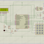
Circuit Diagram

Download
You can download MikroC files and Proteus files here…




Can you cross check whether the oscillator frequency given in mikroc project settings and proteus pic settings are correct ?
Hi. I’m using PIC16F628A and it works just fine in real life, but I got an error on Proteus simulation: “Controller received data whilst busy”.
Do you know a way to solve that issue?
Nicely working without any error. mikroC code is correct
i tried this but not working pls i dont know why
// LCD module connections
sbit LCD_RS at RE0_bit;
sbit LCD_EN at RE2_bit;
sbit LCD_D4 at RD4_bit;
sbit LCD_D5 at RD5_bit;
sbit LCD_D6 at RD6_bit;
sbit LCD_D7 at RD7_bit;
sbit LCD_RS_Direction at TRISE0_bit;
sbit LCD_EN_Direction at TRISE2_bit;
sbit LCD_D4_Direction at TRISD4_bit;
sbit LCD_D5_Direction at TRISD5_bit;
sbit LCD_D6_Direction at TRISD6_bit;
sbit LCD_D7_Direction at TRISD7_bit;
// End LCD module connections
void main()
{
Lcd_Init(); // Initialize LCD
Lcd_Cmd(_LCD_CLEAR); // Clear display
Lcd_Cmd(_LCD_CURSOR_OFF); // Cursor off
Lcd_Out(1,1,”Hello World”); // Write text’Hello World’ in first row
}
hello, how can i use this code for PIC 16F877 ?
i am having a problem.,,a have a aanlog to digitlal converter in which same pattern is followed but display is not working …
sbit LCD_RS at RC2_bit;
sbit LCD_EN at RC3_bit;
sbit LCD_D4 at RC4_bit;
sbit LCD_D5 at RC5_bit;
sbit LCD_D6 at RC6_bit;
sbit LCD_D7 at RC7_bit;
sbit LCD_RS_Direction at TRISC2_bit;
sbit LCD_EN_Direction at TRISC3_bit;
sbit LCD_D4_Direction at TRISC4_bit;
sbit LCD_D5_Direction at TRISC5_bit;
sbit LCD_D6_Direction at TRISC6_bit;
sbit LCD_D7_Direction at TRISC7_bit;
int hamza();
void main()
{
unsigned int x1,x2,x3;
unsigned int z;
unsigned int y;
char b[10];
TRISA0_bit=1;
trisb=0;
trisc=0;
trisd=0;
ADCON1=0b11000100;
ADCON0=0b01000001;
loop:
ADCON0=0b01000001;
x1=hamza();
latb=x1;
ADCON0=0b01001001;
x2=hamza();
latb=x2; //pwehle lat c tha
ADCON0=0b01011001;
x3=hamza();
latd=x3;
Lcd_Init();
Lcd_Cmd(_LCD_CLEAR);
Lcd_Cmd(_LCD_CURSOR_OFF);
FloatToStr(x2,b);
Lcd_Out(1,3,b);
goto loop;
`
}
int hamza()
{
unsigned int jj;
GO_DONE_BIT=1;
while(GO_DONE_BIT==1);
jj=ADRESH;
jj=(jj<<8)|(ADRESL);
return jj;
my business was looking for a form a few weeks ago and was informed of an online service that has a searchable database . If people have been needing it too , here’s a
https://goo.gl/GSryxq.this website is very very useful..thanks for admin…i hope that you’ll get the knowledge too
Tutorials are open, you don’t need to login for that.
how do i download tutorials to my accounts
thanks mate for you paying attention well every thing goes fine the hardware as well there is some configuration is missing in programmer now I fix this after that is working fine thanks again.
Check your LCD connections with respect to program. Try adjusting the contrast adjusting potentiometer.
Where is LED code ?
Above program seems to be correct. Check your hardware connections.
Try this tutorial : https://electrosome.com/matrix-keypad-pic-microcontroller/
The above steps are just defining the pins to which LCD is connected.
after no success i’m trying these codes but still no display only black box on first line also led’s not working with it
// PIC16F72 USING NSP GENIUS TO PROGRAM
// Lcd module connections
sbit LCD_RS at RB1_bit;
//sbit LCD_RW at RB2_bit;
sbit LCD_EN at RB3_bit;
sbit LCD_D4 at RB4_bit;
sbit LCD_D5 at RB5_bit;
sbit LCD_D6 at RB6_bit;
sbit LCD_D7 at RB7_bit;
sbit lcd_RS_Direction at TRISB1_bit;
sbit lcd_RW_Direction at TRISB2_bit;
sbit LCD_EN_Direction at TRISB3_bit;
sbit LCD_D4_Direction at TRISB4_bit;
sbit LCD_D5_Direction at TRISB5_bit;
sbit LCD_D6_Direction at TRISB6_bit;
sbit LCD_D7_Direction at TRISB7_bit;
// End Lcd module connections
// Output connections
sbit Led_2 at RA0_bit;
sbit Led_3 at RA1_bit;
sbit Led_2_Direction at TRISA0_bit;
sbit Led_3_Direction at TRISA1_bit;
// Input connections
sbit IN_1 at RA2_bit;
sbit IN_1_Direction at TRISA2_bit;
char txt1[] = “POWERED BY”;
char txt2[] = “S A H B E E”;
char txt3[] = “O P E N”;
char txt4[] = “C L O S E”;
//Int i; // Loop variable
//i = IN_1;
void Move_Delay() { // Function used for text moving
Delay_ms(500); // You can change the moving speed here
}
void main(){
TRISB = 0;
PORTB = 0xFF;
TRISB = 0xff;
TRISA0_bit = 0xff;
TRISA1_bit = 0x00;
TRISA2_bit = 1;
TRISA.RA0 = 0; //set Port RB0 as output
TRISA.RA1 = 0;
Lcd_Init(); // Initialize Lcd
Lcd_Cmd(_LCD_CLEAR); // Clear display
Lcd_Cmd(_LCD_CURSOR_OFF); // Cursor off
Lcd_Out(1,6,txt1); // Write text in first row
Lcd_Out(2,6,txt2); // Write text in second row
Delay_ms(2000);
Lcd_Cmd(_LCD_CLEAR); // Clear display
// Lcd_Out(1,1,txt1); // Write text in first row
//Lcd_Out(2,5,txt2); // Write text in second row
Delay_ms(500);
LCD_cMD(_LCD_CLEAR);
Lcd_Out(2,5,txt4); // Write text in second row
Move_Delay();
while(1) { // Endless loop //for(;;){ //endless loop
// if(PORTA.RA2 == 1){ //if push button is pressed
// PORTA.RA2 = 1; \toggle LED
for(;;) // PORTA.RA3 = 0;
if (PORTA.RA2 == 1);
{ PORTA.RA1= 0x00;
PORTA.RA0 = 0xff;
Lcd_Cmd(_LCD_CLEAR); // Clear display
Lcd_Out(5,7,txt3); // Write text in first row
}
}
hi i’m using pic16f72 to display 2×16 and 2 led trying to switch on can anybody correct my mistake please because compiler pass out with hex file and i’m using mikroc
that code i’m applying
// LCD module connections
sbit LCD_RS at RC2_bit;
sbit LCD_EN at RC3_bit;
sbit LCD_D4 at RC4_bit;
sbit LCD_D5 at RC5_bit;
sbit LCD_D6 at RC6_bit;
sbit LCD_D7 at RC7_bit;
sbit LCD_RS_Direction at TRISC2_bit;
sbit LCD_EN_Direction at TRISC3_bit;
sbit LCD_D4_Direction at TRISC4_bit;
sbit LCD_D5_Direction at TRISC5_bit;
sbit LCD_D6_Direction at TRISC6_bit;
sbit LCD_D7_Direction at TRISC7_bit;
// End LCD module connections
void main()
{
Lcd_Init(); // Initialize LCD
Lcd_Cmd(_LCD_CLEAR); // Clear display
Lcd_Cmd(_LCD_CURSOR_OFF); // Cursor off
Lcd_Out(1,1,”Hello World”);//Write text’Hello World’ in first row
}
hello, i work with pic16f877a and keypad 4×4, my lcd at portD and keypad at portB, i set LVP disable. my problem is mya keypad is not working,
this is my port setting
ar txt[6];
// Keypad module connections
char keypadPort at PORTB;
// End Keypad module connections
// LCD module connections
sbit LCD_RS at RA5_bit;
//sbit LCD_RW at RA4_bit;
sbit LCD_EN at RA3_bit;
sbit LCD_D4 at RD4_bit;
sbit LCD_D5 at RD5_bit;
sbit LCD_D6 at RD6_bit;
sbit LCD_D7 at RD7_bit;
sbit LCD_RS_Direction at TRISA5_bit;
//sbit LCD_RW_Direction at TRISA4_bit;
sbit LCD_EN_Direction at TRISA3_bit;
sbit LCD_D4_Direction at TRISD4_bit;
sbit LCD_D5_Direction at TRISD5_bit;
sbit LCD_D6_Direction at TRISD6_bit;
sbit LCD_D7_Direction at TRISD7_bit;
// End LCD module connections
void main() {
ADCON1 = 0X0F; //All A to D pin on PortA to digital
CMCON = 0X07; //Disable comparators
TRISA4_bit = 1;
OPTION_REG.B7 = 0;
TRISB = 0;
PORTB.F0 = 1;
PORTB.F1 = 1;
PORTB.F2 = 1;
PORTB.F3 = 1;
PORTB.F4 = 0;
PORTB.F5 = 0;
PORTB.F6 = 0;
PORTB.F7 = 0;
TRISD = 0;
PORTD = 0;
TRISA = 0;
PORTA = 0;
cnt = 0; // Reset counter
Keypad_Init(); // Initialize Keypad
can anyone help me to solved my problem? thanks
by writing the program as below
// LCD module connections
sbit LCD_RS at RC2_bit;
sbit LCD_EN at RC3_bit;
sbit LCD_D7 at RC7_bit;
sbit LCD_D6 at RC6_bit;
sbit LCD_D5 at RC5_bit;
sbit LCD_D4 at RC4_bit;
// End LCD module connections
// LCD Pin direction
sbit LCD_RS_Direction at TRISC2_bit;
sbit LCD_EN_Direction at TRISC3_bit;
sbit LCD_D7_Direction at TRISC7_bit;
sbit LCD_D6_Direction at TRISC6_bit;
sbit LCD_D5_Direction at TRISC5_bit;
sbit LCD_D4_Direction at TRISC4_bit;
// End of LCD Pin direction
how the values are sent to the ports of lcd ?
as 0 or 1?
is this just defining the ports?
like if we want to give the value to D3 as 1 or 0 how to do that?
thanks:)
It means that you don’t have enough memory to use those much ram texts.
Another solution is to use program memory instead of ram as shown below.
const char MSG1[] = “ERROR”;
//…………………………………………………………………
char * CopyConst2Ram(char * dest, const char * src)
{
char * d ;
d = dest;
for(;*dest++ = *src++;);
return d;
}
//……………………………………………………………………………………………………
Lcd_Out(1,1, CopyConst2Ram(msg, UART_txt1));
Sir, i’m using mikroc pro for 8051. In my program, i have to display different comments on the LCD at different stages of the program for the user to see those comments and work accordingly. As such i’m having issues with the RAM. It says “Not enough RAM ‘temp'”. If i reduce the number of letters in the texts to be displayed, the program works fine. Please help. Thank you.
Please try it yourself and you can ask doubts if you have any.
Sir, i want to make dynamic password based security system on lcd and keypad …pls help
RA4 is an open drain output, so you should provide external pull up resistor…
and you should connect RA5 to 5V is the internal pull up of MCLR is not enabled in the program.
I am using PIC16f628a to build a wireless remote to control a robot by interfacing pic with lcd and rf module.
PROGRAM FOR REMOTE MADE OF PIC16F628A IN MIKRO C
sbit LCD_RS at RA4_bit;
sbit LCD_EN at RA7_bit;
sbit LCD_D4 at RA0_bit;
sbit LCD_D5 at RA1_bit;
sbit LCD_D6 at RA2_bit;
sbit LCD_D7 at RA3_bit;
sbit LCD_RS_Direction at TRISA4_bit;
sbit LCD_EN_Direction at TRISA7_bit;
sbit LCD_D4_Direction at TRISA0_bit;
sbit LCD_D5_Direction at TRISA1_bit;
sbit LCD_D6_Direction at TRISA2_bit;
sbit LCD_D7_Direction at TRISA3_bit;
//End LCD module connection
void main()
{
char sw;
CMCON |= 7; // Disable Comparators
TRISA=0x00; //porta as output
TRISB=0xfb; //portb rb2 as output,remaining input
PORTB=0x00; //logic value of portb. clear portb
PORTA=0x00; //clear porta
Lcd_Init();// Initialize LCD (inbuilt library in mikroc)
Delay_ms(100);//stabilize function
Lcd_Out(1,1,”H”);//display H in first row first column
Delay_ms(1000);
RCSTA=0x80; // to enable tx port as serial enanle bit 7
TXSTA=0x20;// transmit 8bit data in asynchronous low speed mode.
Lcd_Cmd(_LCD_CLEAR ); //clear lcd
Delay_ms(1000);
Lcd_Cmd(_LCD_BLINK_CURSOR_ON); //cursor blink on
Delay_ms(1000);
do
{
if(PORTB !=0) //if any switch is pressed
{
Delay_ms(100);//switch debounce
if(PORTB!=0)
{
sw=PORTB;
switch(sw)
{
case 0x01:Lcd_Out(1,1,”F”); //first switch for forward motion display on lcd that if rb0 is high
break;
case 0x02:Lcd_Out(1,1,”B”); break;//f rb1 is high
case 0x80:Lcd_Out(1,1,”L”); break;//if rb7 is high
case 0x08:Lcd_Out(1,1,”R”);break;
case 0x10:Lcd_Out(1,1,”CL”);break;
case 0x20:Lcd_Out(1,1,”CR”);break;
default:break;
}
UART1_Init(1200); //initialize uart
Delay_ms(100);
UART1_Write(sw); //transmit sw at uart pin
Delay_ms(1000);
}
}
}
while(1);
}
i have simulated this code in proteus 7.5version.and also downloaded it to my IC .in both cases LCD just glows,no charecters are displayed.Also serial communication is not working.i have included my circuit.please help.
use : [email protected]
tyuy
// LCD module connections
sbit LCD_RS at RD4_bit;
sbit LCD_EN at RD5_bit;
sbit LCD_D4 at RD0_bit;
sbit LCD_D5 at RD1_bit;
sbit LCD_D6 at RD2_bit;
sbit LCD_D7 at RD3_bit;
sbit LCD_RS_Direction at TRISD4_bit;
sbit LCD_EN_Direction at TRISD5_bit;
sbit LCD_D4_Direction at TRISD0_bit;
sbit LCD_D5_Direction at TRISD1_bit;
sbit LCD_D6_Direction at TRISD2_bit;
sbit LCD_D7_Direction at TRISD3_bit;
// End LCD module connections
void main()
{
Lcd_Init(); // Initialize LCD
Lcd_Cmd(_LCD_CLEAR); // Clear display
Lcd_Cmd(_LCD_CURSOR_OFF); // Cursor off
Lcd_Out(1,1,”Hello World”);//Write text’Hello World’ in first row
}
PLEASE TELL ME WHY THIS CODE IS NOT WORKING
thank u george it’s working perfect! 🙂
Make sure that LCD connections are correct..
Try adjusting the contrast preset..
yeah!i specified 16 mhz in mikroc !in hardware also i m using 16mhz but the microcontroller to lcd connections are different i changed it little bit and also i changed the sbit values as per the program!
sbit LCD_RS at RB1_bit;
sbit LCD_EN at RB0_bit;
sbit LCD_D4 at RB4_bit;
sbit LCD_D5 at RB5_bit;
sbit LCD_D6 at RB6_bit;
sbit LCD_D7 at RB7_bit;
sbit LCD_RS_Direction at TRISB1_bit;
sbit LCD_EN_Direction at TRISB0_bit;
sbit LCD_D4_Direction at TRISB4_bit;
sbit LCD_D5_Direction at TRISB5_bit;
sbit LCD_D6_Direction at TRISB6_bit;
sbit LCD_D7_Direction at TRISB7_bit;
Did you rebuild the project for 16MHz ?
HI,i have tried this code works in proteus but not in real time what is the problem please help!!i m using 16mhz crystal!
I don’t get your question.
i use pic 16f877a controller..if PORTB as a digital input message display “HELLO” if PORTc as s digital input message display “World” here is code but code is not working..
TRISB.F0=0X00;
PORTB.F0=0X00;
CMCON=0x07; //port a digital input
//ADCON1=1;
Lcd_Init();
// Initialize LCD
//Lcd_Cmd(_LCD_CLEAR);
// Clear display
Lcd_Cmd(_LCD_CURSOR_OFF); // Cursor off
Lcd_Out(1,1,”hi”);
if(PORTB.F0==1)
{
Lcd_Out(1,1,”Hello”);
}
Hello,
Sorry, there was a small mistake in the above program which is occurred while updating it..
Now it is corrected. Please try now.
Thanks for commenting..
Hi Ligo, I built this project, but the LCD is only showing a line of black boxes in the second line. But by LCD is working properly with Arduino. MCU is also working in other projects. I double checked the connections. Can you help me please?
Use a 10K ohm preset….. and adjust it after powering the circuit…
how should i connect pin 3 please ?
You can use IntToStr() function…
eg :
char s[7];
int e;
…
…
…
e = 710;
IntToStr(e,s);
Lcd_Out(1,1,e);
hi pls can u tell me how can i display numbers on lcd for example if i wanna make a counter
Use
Lcd_Cmd(_LCD_SHIFT_RIGHT);
and
Lcd_Cmd(_LCD_SHIFT_LEFT);
hello……… I am doing a project with Lcd display. I want to move the first row of lcd from right to left . Can any one help me to do this………
Hello,
The above program is written for MikroC Pro Compiler..
ye its not working for me ether idc why i trayed led blinking to check if my pick works but that didin’t worked too i think my pic burned or i doing something wrong with program. i using pickit 3 and i inserting microC hex file with mplab
Hi sir,
We are doing a project in Company for our final year we wear doing LCD display using same ur code and same ur connections Used 4 bit mode. Tried to compile it and it didn’t work. Error message said: “Expected ‘;’ but sbit LCD_RS found” so I cancelled all the statements before main and changed Lcd_Init();–> Lcd_Init(&PORTB); . Also I omitted the first underscore “_” in the Lcd_Cmd function e.g. Lcd_Cmd(_LCD_CLEAR); –> Lcd_Cmd(LCD_CLEAR); and it worked. But after 2 or 3 days later we are not getting LCD display only except contrast is displayed when we change 10K pot what may be problem pls hep us.We did not change anything pls verify our code we are using pickit2 programmer from 1st we are not able to understand why it is not working now
program is
void main()
{
Lcd_Init(&PORTB); // Initialize LCD
Lcd_Cmd(LCD_CLEAR); // Clear display
Lcd_Cmd(LCD_CURSOR_OFF); // Cursor off
Lcd_Out(1,1,”Hello World”);//Write text’Hello World’ in first row
}
i using pic16f877- 20/P this pic should work with this build? plz repaly
sir,
i already made hardware, and the connection i given have pin RW connected to PIC. how can i program such a connection in Microc PRO? there was a function Lcd_Config() in previous versions
sorry for my english, I am latin. Are you sure you connected all LCD Pins, don’t forget the pin 3 (Vo, it’s the contrast) and also connect the led, pin 15 and 16.
generated hex fle… and it works good with proteous but it is not working practically… any connections to be cautious about???
HEY IM USING PIC18f452 IN MICROC PICKIT 2 WHAT WOULD BE THE CONFIGURATION REG 4 this code ???
can some body help.
sir during building hex file its says “expected ‘;’ bt found ‘rsbit'” what shall i do / and i am using micro c pro
Hey !! Ligo George …. we are doing our FYP project in which we are measuring Voltages and Currents at different nodes of our project…. since these values are continuously changing in our circuit … plz help us that how could we measure real time changing values and show those values on LCD …….
Sorry,, it was a mistake while pasting the code.. It is corrected now..
Thanks.. 🙂
Your circuit diagram does not match your code. RS and E diagram pins do not match the pins in the code.
Sorry, I haven’t yet used it..
hi! Ligo George! Can you help me the program read from CH0-CH7 8 channels of MCP6s28, by Mikro C, I have tried but to no avail, I am urgently, please!
Its ok.. 🙂
sorry, because this was bothering him, perhaps to learn that my self, thanks for all!
Hello,
Sorry.. I have no time to develop projects for each and everyone commenting here…
This discussion forum is to discuss about problems related to above project/tutorial……..
I’ve tried, but not, please help me!, I am looking out for a project!
Please try it yourself……….. It is a time consuming process
Ligo George he may be no better guide? I imagine it’s not like? thank you!
thank very much! Ligo George ^^
As you are using MikroC Pro… use the built in library functions like.. IntToStr(), FloatToStr(), LongToStr()…. but these functions are less efficient….. So try to write your own function.. according to your requirement.
You can display a 1 digit number.. by using its ASCII value…
if ‘a’ is a single digit number (0, 1, 2 … 9)
its ascii value is c = a + 48;
where 48 is the ascii value of c..
this can be displayed by … Lcd_Chr(1,1,c)
For multi digit numbers, you need to display it digit by digit..
LCD interfacing with PIC Microcontroller only show text, i want show value? please!
Read the datasheet of MCP6S28 carefully….. you need to configure its registers accordingly..
In mikroc, can use the SPI library to communicate with the Programmable Gain Amplifier..
please help me! how to read temperatures from channels MCP6S28 PIC 16f887 and display the result on LCD?
MikroC Pro provides built in libraries for interfacing LCDs with HD44780 compliant controllers using 4 bit mode data transmission… Check whether your LCDs controller is HD44780 compliant…
Im using the mikroc library to interface with a lcd 4 lines and 20 rows, with 4-bits comunication, but i have a problem, afeter the code is runing it start to mixed up, how can i do?
Okey thanks
There is no free versions.. try searching cracked ones in torrent..
hey Ligo thank very much for the excellent explainations on interfacing lcd, can you please send me a link where I can download protues free versions to simulate a circuit?
Everything is explained in the code itself… If you have any doubts please ask about that doubt..
is this command also suits for ccs compailer….??
can u xpln this programe.. step by step…
use Lcd_Cmd(_LCD_MOVE_CURSOR_LEFT) in a for loop after the Lcd_Out
i have write this program and whole text is not displayed on LCD
// LCD module connections
sbit LCD_RS at RB0_bit;
sbit LCD_EN at RB2_bit;
sbit LCD_D4 at RB4_bit;
sbit LCD_D5 at RB5_bit;
sbit LCD_D6 at RB6_bit;
sbit LCD_D7 at RB7_bit;
sbit LCD_RS_Direction at TRISB0_bit;
sbit LCD_EN_Direction at TRISB2_bit;
sbit LCD_D4_Direction at TRISB4_bit;
sbit LCD_D5_Direction at TRISB5_bit;
sbit LCD_D6_Direction at TRISB6_bit;
sbit LCD_D7_Direction at TRISB7_bit;
// End LCD module connections
void main() {
Lcd_Init(); // Initialize LCD
Lcd_Cmd(_LCD_CLEAR); // Clear display
Lcd_Cmd(_LCD_MOVE_CURSOR_LEFT);
Lcd_Out(1,1,”Hello World what is going on this time”);//Write text” in first row
You can use the command: Lcd_Cmd(_LCD_MOVE_CURSOR_LEFT) or Lcd_Cmd(_LCD_MOVE_CURSOR_RIGHT)
in this lcd interfacing you have write comment “HELLO WORLD” . IF i want to write comment on lcd ” Early to bed and early arise makes a man healthy ” it is large comment . now this should move on lcd so that whole comment could be shown what should i do?
You can follow our tutorials…. If you have any doubts, just comment ..
Sir,
I am very interested in learning PIC Programming. Can you please help me. I shall be very thankfull to you.
ok Thanks
I think you are using an old version of mikroC………… Use MikroC Pro…
Used 4 bit mode. Tried to compile it and it didn’t work. Error message said: “Expected ‘;’ but sbit LCD_RS found” so I cancelled all the statements before main and changed Lcd_Init();–> Lcd_Init(&PORTB); . Also I omitted the first underscore “_” in the Lcd_Cmd function e.g. Lcd_Cmd(_LCD_CLEAR); –> Lcd_Cmd(LCD_CLEAR); and it worked. Any Idea why the original program didn’t work? Where did I go wrong?