Using ADC Module of PIC Microcontroller – Hi Tech C
Contents
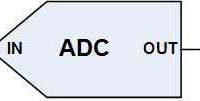
Analog to Digital Converter (ADC) is a device that converts an analog quantity (continuous voltage) to discrete digital values. This is very useful when we want to do some processing on physical quantities, which are normally analog in nature. Most of the PIC Microcontrollers have built in ADC Module. Here we are using PIC 16F877A for demonstrating the working.

ADC of PIC Microcontrollers have 5 inputs for 28 pin devices and 8 inputs for 40/44 pin devices. It is a 10-bit ADC, ie the conversion of analog signal results in corresponding 10-bit digital number. The positive and negative reference voltage (+Vref and -Vref) of PIC ADC is software selectable, which can be VDD, VSS, voltage at RA2 or RA3. This A/D Converter module can also operate in sleep mode in which clock is derived from its internal RC oscillator. Following points may help you to understand the concept of reference voltages.
- When the ADC input is -Vref, result will be 0000000000
- When the ADC input is +Vref, result will be 1111111111
- Resolution of ADC = (+Vref – -Vref)/(210 – 1), which is the minimum voltage required to change the ADC result by one bit.
- Here ADC Resolution = (5 – 0)/(1024 – 1) = 5/1023 = 0.004887V
- So, if the input is 5V, ADC Value is 5/0.004887 = 1023 = 11111111 (binary)
- If the input is 0.004887V, ADC Value is 0.004887/0.004887 = 1 = 00000001 (binary)
We require some hardware knowledge to program PIC ADC in Hi-Tech C. If you don’t need hardware knowledge please skip this part and go to Circuit Diagram.
ADC Module in Detail
Registers
PIC ADC has 4 registers :
- ADCON0 – ADC Control Register 0
- ADCON1 – ADC Control Register 1
- ADRESH – ADC Result High Register
- ADRESL – ADC Result Low Register
ADCON0 Register

- ADCS1 and ADCS2 are used to select A/D Conversion Clock. It should be selected in accordance with device clock.
- CH2, CH1 and CH0 are used to select one of the analog input channel out of eight channels.
- GO/DONE is the A/D Conversion Status bit. Setting this bit initializes A/D Conversion and will be automatically cleared when the conversion is complete.
- ADON is used to switch on/off the ADC Module. When it is 1, the ADC Module turns ON and when it is 0, the ADC Module will be OFF.
ADCON1 Register

- ADFM is the ADC Result Format select bit. Two 8 bit register (ADRESH and ADRESL) are provided to store the 10-bit result of A/D Conversion, thus we need’t use 6 bits. When ADFM is 1, the result will be right justified, ie Most Significant Bits of ADRESH will be read as 0. When ADFM is 0, the result will be left justified, ie Least Significant Bits of ADRESL will be read as zero.
- ADCS2 is used to select A/D Conversion Clock in association with ADCS1 and ADC2 of ADCON0 register.
- PCFG3 – PCFG0 are the A/D Port Configuration Control bits. Each pin amoung AN0 – AN7 is configured as analog, digital or reference voltage inputs according to the status of these configuration bits as given below.

Note : TRIS Registers of Analog inputs must be configured as input for the proper operation.
ADC Block Diagram

Selection of A/D Conversion Clock
The time for A/D Conversion per bit is defined as TAD and it requires minimum 12TAD to generate the 10-bit result. The time TAD is determined by the A/D Conversion Clock which is software selectable to following options.
- 2 TOSC
- 4 TOSC
- 8 TOSC
- 16 TOSC
- 32 TOSC
- 64 TOSC
- Internal RC oscillator of ADC Module
TOSC is the time period of the device clock usually provided by the crystal oscillator.
Care should be taken while selecting the A/D Conversion Clock, such that the clock should provide the minimum TAD (1.6μS) required for the correct A/D Conversion. So refer the following table before setting the ADC clock.

Circuit Diagram

I hope that you already go through our first tutorials, so I am not going to explain deeply about the circuit. The reference voltages of ADC is set to VDD (5V) and VSS (GND) though software (code given below). Analog input is given to Channel 0 using a potentiometer, thus we can vary the ADC input voltage from VSS to VDD. The 10-bit result of ADC is displayed using 10 LEDs, and 470Ω resistors are used to limit current through them.
Hi-Tech C Code
#include<htc.h>
#include<pic.h>

#define _XTAL_FREQ 8000000

void ADC_Init()
{
  ADCON0 = 0x41; //ADC Module Turned ON and Clock is selected
  ADCON1 = 0xC0; //All pins as Analog Input
                 //With reference voltages VDD and VSS
}

unsigned int ADC_Read(unsigned char channel)
{
  if(channel > 7) //If Invalid channel selected
    return 0;     //Return 0

  ADCON0 &= 0xC5; //Clearing the Channel Selection Bits
  ADCON0 |= channel<<3; //Setting the required Bits
  __delay_ms(2); //Acquisition time to charge hold capacitor
  GO_nDONE = 1; //Initializes A/D Conversion
  while(GO_nDONE); //Wait for A/D Conversion to complete
  return ((ADRESH<<8)+ADRESL); //Returns Result
}

void main()
{
  unsigned int a;
  TRISB = 0x00; //PORTB as output
  TRISC = 0x00; //PORTC as output
  TRISA = 0xFF; //PORTA as input
  ADC_Init(); //Initializes ADC Module

  do
  {
    a = ADC_Read(0); //Reading Analog Channel 0
    PORTB = a; //Lower 8 bits to PORTB
    PORTC = a>>8; //Higher 2 bits to PORTC
    __delay_ms(100); //Delay
  }while(1); //Infinite Loop
}
I think the program is completely explained through its comments. If you have any doubts please comment below.
You can download Hi-Tech C and Proteus files here…




https://electrosome.com/analog-to-digital-converter-pic/
I want to learn adc code with micro c programming, can you teach?
sir, im getting confused ON ADCON0&=0XC5; what is the c5
I want adc based delay timer code using xc8
Using trimpot i want to adjust the time delay at output
There are hundreds of reasons for this error…. Please provide detailed information.
I am a fresher in Programming.
I got an error as shown below. Please help me to solve this.
Thanks in Advance
nbproject/Makefile-impl.mk:39: recipe for target ‘.build-impl’ failed
make[2]: *** [build/default/production/ADC USING PIC16F877A.p1] Error 1
make[1]: *** [.build-conf] Error 2
make: *** [.build-impl] Error 2
BUILD FAILED (exit value 2, total time: 2s)
its amazing guidelines by you……………we are want to more learning about your tutorials
so give us more than more information related to MPLAB
Kindly use our forums ( https://electrosome.com/forums/ ) for asking doubts outside the scope of above article.
Hi everyone, I have a homework for my studies and I was wondering if some of you could give me a hand :
With a PIC16F18855, make a program that uses the analog-to-digital converter (RA4 pin)
connected to the potentiometer. Left wedging is used. Completely explain the sequence of CAN use.
Make a program that uses a PWM to vary the intensity of the LED.
Completely explain the sequence of use of the PWM.
Thank you in advance
Please check the corresponding register definition after converting these value to binary.
Hi, you can choose them basing on the microcontroller registers configuration. You can find all the necessary informations in the MCU data sheet, in the ADC section.
ADCON0 = 0x41; //ADC Module Turned ON and Clock is selected
ADCON1 = 0xC0; //All pins as Analog Input
Can anyone explain these lines??
how we chose these hex values??
is there any calculations there???
Hello Ligo, I’m very new to The world of pic and I’m building an Ats which will display the current and voltage on the output of the Ats on an LCD screen of 16×2. Pls I need help. I’ve chose a 16f877a pic for this project and a 12mhz crystal oscillator and also done some design but I wnt know how to start writing the code. I have the programs like mikroC, Proteus, c++, national instruments, microchip but I need an instructor. Pls help
post the complete code.
Please use our forums https://electrosome.com/forums for asking doubts outside the scope of above article.
Please read above article clearly and understand the working of ADC module. Then you can easily do it.
Just try this a=(((float)a*5000)/1023);
while(1)
{
msCounter++;
UpdateTimeCounter();
if(msCounter==0)
DisplayTime();
a=Adc_read(0);
}
Here i am able to read adc value but no time display.
When i am commenting a=Adc_read(0); Time gets display.
sir i want to connect two different sensors to adc like lm35 & heartbeat sensor. so how to configure the adc for it
Now I am able to receive the linear count of ADC I.e O at 0V and 1023 at 5V.
But when I try to convert it in mili volt.
I.e a=ADC_read(0);
a=((a*5000)/1023);
WriteCommandToLcd(0x80);
WriteDataTolcd(a/1000+48);
WriteDataTolcd(((a/100)%10)+48);
WriteDataTolcd (((a/10)%10)+48);
But I am getting 5,16,35,44,56,61. Three times till I increase the pot to 5v or full.
Sorry, I don’t understand your doubt. Please explain in detail. What is the input you provided ?
sir i am getting rolover of 4 to 5 reading. 128,156,232,etc.
hence i am not getting linear 0 to 1023 count with 0 to 5V instead of that 128,156,232 again repeating this reading till 5v
ADC value is already digital.
HI,
That question is outside the scope of above article. Please use our forums ( https://electrosome.com/forums ) for asking such questions.
You can use MikroC, CCS C, Hi-Tech C or MPLAB XC8. If you are a beginner, better go for MikroC.
https://electrosome.com/category/tutorials/pic-microcontroller/mikroc/
Sir i want to first convert analog data coming to digital using adc and then send this data to pc seriallly..
please can you tell me the code for the same
how can I use external interrupt to measure the AC frequency?
I want to read the AC voltage and display the result on LCD using PIC 16f877a. Which software I should use for Coding.
You can use an instrumentation amplifier for that.
Sir i want to interface loadcell using pic 18f4550.Plz tell me about this
ADCON1 for setting each pin as digital or analog. Example is provided above itself. Please try to understand it.
Configure ADCON1?? or ADCON0, please example
Configure ADCON1 to choose which of the pins are ADC.
Then just call like this ADC_Read(0), ADC_Read(1) .. .etc
What if i want to use multiple AN inputs (for multiple conversions) how should the CHS bits in ADCON0 register be configured ?
Sorry, I don’t understand you. Please elaborate.
I am interfacing 24 bit ADC with micro controller and 500kg load cell please send sample code
how can i alter the code for
1. _XTAL_FREQ of 4000000 with Fosc/4
2. if i want to display the binary values in 4 LED diaply rather than see the led glow
Hello,
Above article is not related to 8051. Please use our forums https://electrosome.com/forums for asking doubts not related to above topics.
i don’t want to say anything else about this explanation THAN THANK YOU
Hi sir, ..I m having small doubt on i2c protocol in 8051
Correct me if i m wrong sir
Actually in i2c communication(ie with DS1307 RTC),i hav doubt in write & read operation sir
What indicates a write operation?
My guess:Whenever SCL moves from high to low,data on SDA goes to slave(ie master as transmitter(8051) & slave as DS1307)
What indicates a Read operation?
My guess:Whenever SCL moves from low to high,data on SDA goes to Master( ie slave as TransmitterDS1307 & master as 8051)
This is the below program i got from net sir,Pls correct if i m wrong
/*———————————————————————————*
void I2C_Write(unsigned char dat)
———————————————————————————-*
* I/P Arguments: unsigned char–>8bit data to be sent.
* Return value : none
* description :This function is used to send a byte on SDA line using I2C protocol
8bit data is sent bit-by-bit on each clock cycle.
MSB(bit) is sent first and LSB(bit) is sent at last.
Data is sent when SCL is low.
———————————————————————————–*/
void I2C_Write(unsigned char dat)
{
unsigned char i;
for(i=0;i<8;i++)
{
SDA = dat & 0x80; //Here i understand that we ANDing with 0x80 to
I2C_Clock(); // send MSB first.& data is shifted for 8 times.
dat = dat<<1; // But my question is they want to set the SCL
} // as HIGH to LOW na,,but they didnt.
SDA = 1; // Similarly y they setting SDA=1
}
/*———————————————————————————–*
unsigned char I2C_Read()
————————————————————————————*
* I/P Arguments: none.
* Return value : Unsigned char(received byte)
* description :This fun is used to receive a byte on SDA line using I2C protocol.
8bit data is received bit-by-bit each clock and finally packed into Byte.
MSB(bit) is received first and LSB(bit) is received at last.
————————————————————————————-*/
unsigned char I2C_Read(void)
{
unsigned char i, dat=0x00;
SDA=1;
for(i=0;i<8;i++) //Similarly here y they mentioned about
{ // SCL (high to low,)
delay_us(1);
SCL = 1;
delay_us(1);
dat = dat<<1;
dat = dat | SDA;
SCL = 0;
}
return dat;
}
SIR PLS HELP ME SIR,WAITING FOR UR REPLY..THANKS IN ADVANCE
a&=b is equal to a = a & b, where & is the bitwise AND operator.
Similarly a|=b is equal to a = a | b, where | is the bitwise OR operator
<< is the left shifting operator, a = a << 3 shifts the bits of a left by 3 bits.
Please let us know parts that you don’t understand.
hi i could not understand this symbol (&=) AND (I=) in ADCONO &= 0*C5 and ADCONO I=CHANNEL<<3 SO PLZ EXPLAIN ME THE SYMBOLS IN BRAKETS
hi i want to know every step comments of the hi tech c program ” using ADC module of pic microcontroller -Hi Tech c” because i am unable to understand some of the step in this program
Fist add it to your project file list in the IDE .. then include it in your program.
i just don it , but i cant able to add
You can read multiple channels without any errors… Make sure that you provided enough acquisition time.
#include
#include
#include
__CONFIG (0x3F32);//………………CONFIGURE BIT………
// #define krl1 RD6
// #define krl2 RD5
// // #define krl3 RD4
// #define krl4 RD3
// #define krl5 RD2
// #define krl6 RD0
// // #define krl7 RD1
#define krl1 RD6
#define krl2 RD5
// #define krl3 RD4
#define krl3 RD3
#define krl4 RD2
#define krl5 RD0
// #define krl7 RD1
unsigned char ds1,ds2,ds3,ds4,key_code,scan_no,kr_count,debounce,key_ready,nkp,key,start,key_15;
unsigned char lut[]={0xfc,0x60,0xda,0xf2,0x66,0xb6,0xbe,0xe0,0xfe,0xf6,0xee,0xfe,0x9c,0x7a,0x9e,0x8e,0xff};
interrupt void isr_t0();
void scanner();
void init_timer0();
void k();
void init_keypad();
#define bl RB0
#define rs RB1
#define rw RB2
#define en RB3
void init_lcd();
void wr_lcd_cw0(unsigned char);
void wr_lcd_cw(unsigned char);
void wr_lcd_cw(unsigned char);
void wr_lcd_dw(unsigned char);
void delay_ms(unsigned int);
void disp_string(unsigned char *);
unsigned char count;
unsigned char ascii[] = {“0123456789abcdef”};
#define lp RC4
#define hp RC5
//……………………………………………………..
void init_adc();
unsigned int read_adc(unsigned char );
void conv();
void temp_display();
unsigned char rec_data, count;
unsigned int adc_data,ms_vtg,temp,adc_data1,deg,adc_data2,adc_datax;
float vtg;
void temperature();
void temp_check();
//…………………………………………
void next_key();
void mode();
bit mode_out,alt;
unsigned char blink,win_sel,fan_inc,max_temp,min_temp;
void fan();
void temp_setting();
//……………………………………………………..
void wr_ep(unsigned char ,unsigned char );
unsigned char read_ep(unsigned char);
unsigned char ep_data,ep_data1,ep_data2;
//**************************************************************
//&&&&&&&&&&&&&&&&&&&&&&&&&&&&&&&&&&&&&&&&&&&&&&&&&&&&&&&&&&&&&&&&&
unsigned int RawADC;
long Resistance;
double Temp_x;
void temperature_x();
void temp_display_x();
void main()
{
TRISB=0x00;
init_keypad();
init_timer0();
init_lcd();
init_adc();
while(1)
{
temperature();
delay_ms(2000);
init_adc();
temperature_x();
}
}
//…………………………..main end…………………
void temperature_x()
{
// Assuming a 10k Thermistor. Calculation is actually: Resistance = (1024/ADC)
adc_data1= read_adc(0);
RawADC = adc_data1;
Resistance=((10240000/RawADC) – 10000);
/******************************************************************/
/* Utilizes the Steinhart-Hart Thermistor Equation: */
/* Temperature in Kelvin = 1 / {A + B[ln(R)] + C[ln(R)]^3} */
/* where A = 0.001129148, B = 0.000234125 and C = 8.76741E-08 */
/******************************************************************/
Temp_x = log(Resistance);
Temp_x = 1 / (0.001129148 + (0.000234125 * Temp_x) + (0.0000000876741 * Temp_x * Temp_x * Temp_x));
Temp_x = Temp_x – 273.15; // Convert Kelvin to Celsius
temp_display_x();
//$$$$$$$$$$$$$$$$$$$$$$$$$$$$$$$$$$$$$$$$$$$$$$$$$$$$$$$$$$$$$$$$$$$$
}
void temp_display_x()
{
adc_datax = Temp_x;
wr_lcd_cw(0xc0);
disp_string(“temp_x”);
wr_lcd_dw(‘:’);
wr_lcd_dw(ascii[(adc_datax/10)]);
wr_lcd_dw(ascii[(adc_datax%10)]);
// delay_ms(1000);
}
void next_key()
{
// wr_lcd_cw(0x01);
// wr_lcd_cw(0x84);
// disp_string(“GOOD DAY”);
// wr_lcd_cw(0xc2);
// disp_string(“HAVE A DRINK”);
while(nkp ==0);
nkp =key_ready =0;
while(key_ready==0)
{
temperature();
temp_check();
//temp_low();
}
}//………………………next key…………….
void temperature()
{
// stop = 1;
// while( 1)
// {
adc_data1= read_adc(1);
conv();
delay_ms(1000);
// wr_lcd_cw(0x80);
temp_display();
delay_ms(2000);
//}//end of the while(1)
}
void conv()
{
vtg = (((5.0/1023.0)*adc_data1));
ms_vtg = (vtg *100);
// deg =(ms_vtg/10);
}
//…………………display temp………………………………………………
void temp_display()
{
adc_data2 = ms_vtg;
wr_lcd_cw(0x80);
// disp_string(“temp”);
// wr_lcd_dw(‘:’);
//
// wr_lcd_dw(ascii[(adc_data2/10)]);
// wr_lcd_dw(ascii[(adc_data2%10)]);
//// delay_ms(1000);
disp_string(“V1”);
wr_lcd_dw(‘:’);
wr_lcd_dw(ascii[(adc_data2/100)]);
wr_lcd_dw(‘.’);
wr_lcd_dw(ascii[((adc_data2%100)/10)]);
wr_lcd_dw(ascii[(adc_data2%10)]);
// delay_ms(1000);
}
//+++++++++++++++++++++++++++++++++++++++++++++++++++++++++++++++++++++++++++
// void conv()
// {
//
// vtg = (((5.0/1023.0)*adc_data1));
// ms_vtg = (vtg *1000);
// deg =(ms_vtg/10);
// }
////…………………display temp………………………………………………
// void temp_display()
// {
// adc_data2 = deg;
// wr_lcd_cw(0x80);
// disp_string(“temp”);
// wr_lcd_dw(‘:’);
//
// wr_lcd_dw(ascii[(adc_data2/10)]);
// wr_lcd_dw(ascii[(adc_data2%10)]);
//// delay_ms(1000);
//
// }
//###############################basic function#########################################################
void init_adc()
{
ADCON1 = 0X40;
TRISA = 0XFF;
}//end of the void init_adc()
//——————————————————
unsigned int read_adc(unsigned char ch)
{
unsigned int adc_data,adc_high;
unsigned char adc_low;
ADCON0 = (ch<<3)|(0x01); // A/D convertor & channel 0
delay_ms(20);
ADCON0 = ADCON0 | 0X04; // START CONVERSION (ADON = 1 , GO = 1)
// delay_ms(6);
while((ADCON0 & 0X04) != 0)
{
adc_high = ADRESH;
adc_low = ADRESL;
adc_data = ((adc_high <> 6);
delay_ms(10);
}//end of the while()
ADRESH = ADRESL=adc_low=adc_high=0x00;
ADCON0 = 0X00; // conversion off
// delay_ms(6);
return(adc_data);
}//end of the unsigned char read_adc()
//……………………………….keypad………………………………..
void init_timer0()
{
T1CON=0x00;
TMR1H=0xfc;
TMR1L=0x18;
TMR1ON = 1;
TMR1IE=1;
PEIE=1;
GIE=1;
}
//==================================
interrupt void isr_t0()
{
TMR1IF=0;
scanner();
TMR1H=0xfc;
TMR1L=0x18;
}
//=======================================
void init_keypad()
{
scan_no=0;
ds1=ds2=ds3=ds4=0;
nkp=0;
key_ready=0;
kr_count=20;
debounce=21;
}
//=======================================
void scanner()
{
switch(scan_no)
{
case 0:
key = krl1;
k();
scan_no = 1;
break;
case 1:
key = krl2;
k();
scan_no = 2;
break;
case 2:
key = krl3;
k();
scan_no = 3;
break;
case 3:
key = krl4;
k();
scan_no = 4;
break;
case 4:
key = krl5;
k();
scan_no = 0;
break;
// case 5:
//
// key = krl6;
// k();
// scan_no = 0;
// break;
// case 6:
// key = krl7;
// k();
// scan_no = 7;
// break;
//
// case 7:
//
// key = krl7;
// k();
// scan_no = 0;
// break;
//
}//end of switch case…
}//end of scanner
//======================================
void k()
{
if (key_ready == 1)
{
if (key == 0) //——————–release
{
kr_count = 20;
}
else
{
kr_count–;
if (kr_count == 0)
{
nkp = 1;
kr_count = 20;
}
}
}
else
{
if (debounce == 21)
{
if (key == 0)
{
debounce–;
}
}
else
{
debounce–;
if (debounce == 0)
{
if (key == 0 )
{
key_ready = 1;
key_code = scan_no;
debounce = 21;
}
else
{
debounce = 21;
}
}
}
}
}// end of k…
void init_lcd()
{
delay_ms(15);
wr_lcd_cw0(0x30);
wr_lcd_cw0(0x30);
wr_lcd_cw0(0x30);
wr_lcd_cw0(0x20);
wr_lcd_cw(0x28);
wr_lcd_cw(0x0e);
wr_lcd_cw(0x06);
wr_lcd_cw(0x01);
bl = 0;
}
void wr_lcd_cw0(unsigned char ch)
{
delay_ms(5);
rs = 0;
rw = 0;
PORTB=((PORTB&0X0F)|(ch&0XF0));
en = 1;
delay_ms(1);
delay_ms(1);
delay_ms(1);
en = 0;
}
void wr_lcd_cw(unsigned char ch)
{
delay_ms(5);
rs = 0;
rw = 0;
PORTB=((PORTB&0X0F)|(ch&0XF0));
en = 1;
delay_ms(1);
delay_ms(1);
delay_ms(1);
en = 0;
PORTB=((PORTB&0X0F)|((ch<<4)&0XF0));
en = 1;
delay_ms(1);
delay_ms(1);
delay_ms(1);
en = 0;
}
void wr_lcd_dw(unsigned char ch)
{
delay_ms(5);
rs = 1;
rw = 0;
PORTB=((PORTB&0X0F)|(ch&0XF0));
en = 1;
delay_ms(1);
delay_ms(1);
delay_ms(1);
en = 0;
PORTB=((PORTB&0X0F)|((ch<<4)&0XF0));
en = 1;
delay_ms(1);
delay_ms(1);
delay_ms(1);
en = 0;
}
void delay_ms(unsigned int i)
{
unsigned int j,k;
for(j=0;j<i;j++)
{
for(k=0;k<40;k++);
}
}
void disp_string(unsigned char *ch)
{
count=16;
while(*ch!='')
{
wr_lcd_dw(*ch);
ch++;
count–;
if(count==0)
{
wr_lcd_cw(0xC0);
}
}
}// end of the void disp_str(unsigned char *ch)
//————————————————–
void wr_ep(unsigned char ep_data1,unsigned char address)
{
while(WR != 0);
EEADR = address ; //address
EEDATA = ep_data1;
EEPGD = 0; // data memory
WREN = 1; //enable
EECON2 = 0x55;
EECON2 = 0xAA;
WR = 1;
WREN = 0;
EEIF = 1;
WR = 0;
}//end of the void wr_ep()
//————————————————–
unsigned char read_ep(unsigned char address)
{
EEADR = address;
EEPGD = 0;
RD = 1;
ep_data2 = EEDATA;
return(ep_data2);
}//end of the void read_ep()
//————————————————–
hiii when i use single adc channel at a time my entire circuit and program work properly but when i use two adc channel at a time and call both channel in void main my data gets corrupted in short i am not able to collect two analog data from two different channel and display them once
Just make a file with extension .h.
how to create and add an hrader file to mplab ide for pic 16f877a
thanku
You can’t directly compare the voltages… You should compare it with corresponding ADC values..
Good evening everyone,
I’m just stuck with this…
I want to adquire the signal from a temperature sensor, which is LM35, the signal it provides is 10 mV / ° C, so I would like to know , with the program you posted, the following:
– The Microcontroller can process the voltage input just as it enters through RA 1. Fo example, the temperature is 30°C, then the voltage on LM35 output will be 0.3 mV.
– Based on your program I would like to write this on the “DO” loop:
if (a=0.31)
{
if (a>0.4)
{
Portb = b’00000111′}
Portb = b’00000011′}
That is because I want to activte three diferent relays depending on the temperature.
Thanks a lot!!
pleas can you help me
I need c code to make a calculator for pic18f452
pls corrct me if i m wrong
1)Initially channel has a value 0(means 00000000 ie 1 byte)
2)my doubt is if we shift 00000000 3 times,same only come na
3)i think we shifting ADCON0…This only confusing me sir
The variable “channel” is shifting and OR ed with ADCON0.
AND ing will clear the Channel Selection bits without affecting other bits of ANCON0
OR ing will set required Channel Selection bit without affecting other bits of ANCON0.
2)ADCON0 |= channel<<3
means (0x41) | <<3
01000001(0x41)
00001000.(here i just shifted left 3 times but according to the comment —a = ADC_Read(0); //Reading AnalogChannel 0-means whether u shifting the channel 0 or shifting ox41)
—————What is the neccessary of the result(that is doing OR operation of 0x41 & shifting term
Hats off to u sir..i understood.Thanks for the Crystal clear explanation
You are correct…. …
Firstly ADC value is not voltage… It just a digital (here 10 bit) representation only…
The correct explanation is as below.
ADC Resolution = (+Vref – -Vref)/(2^10 – 1) = (5 – 0)/(1024 – 1) = 5/1023 = 0.004887
So ADC Value corresponding to 2V input is 2/0.004887 = 409.
When the input voltage is 0.004887V, adc value will be 0.004887/0.004887 = 1 .. which is equal to binary 00000001
You can mail your codes to [email protected]ome.com. It will be published with your name.
can you please help give the following questions answer?
Two sixeen bit numbers are stored at 70h,71h and 80h81h in the internal SRAM of Atmega16, with lower memory location having the lower 8-bits of the number. Write ALP to Add these two numbers and store the result at 60h(highest byte),61h and 62h(lower byte).
i m having doubt on AND OR operation of bits
1)ADCON0 &= 0xC5 means ADCON0(0x41) & 0xc5
so it will look like 01000001(0x41)
11000101(0xc5)
——————–
01000001 (Ans in binary-0x41)
2)ADCON0 |= channel<<3
means (0x41) | <<3 (actually here how it come sir?)my guess 01000001(0x41)
00001000(actually i know i m wrong ..here i just shifted left )
———————-
01001001(really want help if i m out of the world)
Actually i have one doubt sir..for adc calculation=(i/p voltage/ref voltage)*1023
so if the input voltage is 2v,reference is 5v,then adc will be=(2/5)*1023=409v.
in binary the value is 0110011001..Am i correct or not..but how here,when the input is 0.04887V … 0000000001
hi ,,i think u might be telling Automatic pf correction…sorry i hav no idea about that deepa
Hello divya
Have u made apfc circuit in the past
Thanks. I made it in mikroc with the help of your program for pic12f675 MUC. I’ll upload for others soon.
ya got it sir…understood .Thanks for spending time
Use device specific header file.. eg: #include
i too have same error,what is the header file
Super sir..i understood perfectly….thank you so much sir
Check the function for ADC Reading. Its prototype :
unsigned int ADC_Read(unsigned char channel)
Which enables us to read any channels in the program… So it need to set the channel every time when we call that function. If you want to read only one channel throughout the program.. you can delete those steps.
sir sorry for asking silly questions…since i m newbie to pic,.
ADCON0 &= 0xC5; //Bitwise AND Operation Clearing the Channel Selection Bits(Y WE NEED TO CLEAR THE CHANNEL)
ADCON0 |= channel<<3; //Bitwise OR Operation for Setting the required Bits(Y WE NEED TO SET,,ACTUALLY CHANNEL ALREADY SELECTED IN ADCON0(CHS2,CHS1,CHS0—-)IN THIS CASE IT WILL BE 000(ANO)…SO Y WE AGAIN SETTING THE CHANNEL..
It is clearly explained in the first paragraph…
Here -Vref = 0 and +Vref = 5V
So when the input is 0V .. ADC Value will be 10 bit .. 0000000000
when the input become 5V … .1111111111
when the input is 0.04887V … 0000000001
ADCON0 &= 0xC5; //Bitwise AND Operation Clearing the Channel Selection Bits
ADCON0 |= channel<<3; //Bitwise OR Operation for Setting the required Bits
hi ligo tis is divya from chennai..want ur help to study about pic 16f877a…i m having doubt on conversion of analog to digital…if some analog(voltage) value is given to pic16f,what exactly pic do?
1) whether it convert to digital or hexa
2) what is the use of ox30 in conversion(usually in other pgm)
3) PORTB = a;//here actually what “a” has?????????????????
sorry if i m confusing u sir…pls help
i m confused about this “ADCON0 &= 0xC5″…what it means..in adcon 0xc5 refers to fosc/8 ,GO/ADON=1…but what is the use of”&”
Hello, the above program is for Hi-Tech C, not for mikroc.
Use the following link.
https://electrosome.com/analog-to-digital-converter-pic/
Good program. Thats why i joined you.
I am a beginner in programming. Using PIC18F4550, trying to program ADC with Mikro C with your above mentioned code. Resulting LEDs behavior is not smooth. Blinking is random. Can you help Ligo George?
It should work without any problems..
Add a delay in while loop..
As your doubt is out of about topic, please use our forums https://electrosome.com/forums for more support.
@lijoppans:disqus
I am trying to control speed of dc motor using potentiometer and for some reason the motor in the simulation is not moving at all could you help me out?
Yes, you can use above functions for all channels..
If i configure a another channel means same step following above your program.ex channel 1,2,3….
You can use above library for that. You can ask doubts here…
I have a Load cell of 200 Kg (S-Type, Make ADI). I want to integrate it to PIC 16F877A through ADC. I need to show Load in xxx.xx (Kg) format. Can you please help on this….I am using Hi-tech C compiler.
Try including pic.h or.. device specific header file like 16f877a.h
What is the header file for GO_nDONE? The compiler always says it is undefined.
It is defined in the header file. It is the second bit of ADCON0 register..
ADRESH => Result High Register
ADRESL => Result Low Register
Total Result Will be : ADRESH:ADRESL where both are 8 bit registers.
We should shift ADRESH left 8 positions and add ADRESL to get actual result.
It sets channel bits in the register ADCON0… <<3 shifts channel left by 3 binary positions..
Explain GO_nDONE. Where is the declaration.?
return ((ADRESH<<8)+ADRESL);
elaborate these lines also sir
channel<<3 means which channel bit to be set
Setting channel selection bits is done using bitwise OR operator.. any bit of a particular register can be made 1 just by doing OR operation with 1. But we can’t make any bits 0 using OR operator if it is already 1. .so we should use AND operator for clearing bits..
ADCON0 &= 0xC5; //Clearing the Channel Selection Bits
ADCON0 |= channel<<3; //Setting the required Bits
Sir Please elaborate these two lines
hi sir,
i got an following errors
(890) Your evaluation period has ended. To continue to experience maximum performance, contact HI-TECH Software to purchase a license. (warning)
Error [192] H:second yearPHASE 2ADC1.c; 19.1 undefined identifier “GO_nDONE”
Error [285] H:second yearPHASE 2ADC1.c; 39.1 no identifier in declaration
Warning [374] H:second yearPHASE 2ADC1.c; 39.1 missing basic type; int assumed
Error [314] H:second yearPHASE 2ADC1.c; 39.1 “;” expected
Hi Ligo George,
please how can i program pic16f88 to be able to measure voltage current sampling ? I need it to track mppt of a 12V solar panel. I have written one program in hitech c, but not measuring anything.
Cheers.
getting error.. undefined identifier “GO_nDONE”
how to rectify it?
how to connect the output of water level indicator to pic 16f877a using internal adc plz help me…
am working on pic16f877a.. a am basically making a sound level meter. so after i acquire the analog signal to digital and store it in the register, i need to convert that into decibels. how to do that? look-up table?
Hi… im working with PIC16f72 …8 bit adc resolution and adc is going well and i want to change the adc value (e.g.0-255) into range (0000-3300) on 4 digit 7 segment display..so plz anybody help how to change it in that range.
4 indicates.. 4th channel of ADC… There was an error in the above program.. which is corrected..
I have read ur tutorial on ADC for hi-tech c complier.I have a doubt in the function called a= adc_read(4),What 4 indicates??
Refer the pin diagram of pic 16f88… you can use pins AN0, AN1, AN2 etc..
Ligo, please I need you to explain to me which of the leg pic16f88 can I connect current sensing from my op-amp to and voltage sensing from my voltage divider ? I am confused about the legs which I will connect them to. I am designing dc-dc boost converter taking my source from solar panel. thanks
nice explanation, kudos to you
Hello, your logic is correct….. so it will work.. if you properly written the code..
Im working with pic16f1788.. In this pic, I configured the ADCON0 to give 10bit result. so the resolution will be 1024. i directly checked the value of the variable ‘a’ like(a256 && a<512, etc etc..) using if statement. But it didn't work. Kindly help me.
Hello, i would like to light LED based on the voltage level like a level indicator. how can i configure in software? may be 5 LED’s to show the voltage level from 0V to 5V..
PIC 16F877B ??? I can’t find that microcontroller…
alright,thank you.
there should be no differences in the code while using PIC16f877A and PIC16f877B right?
Just ignore the least significant two bit.. you will get 8 bit resolution output..
ie, if ‘adc’ is the 10 bit value… then try
adc = adc>>2;
could you please explain how to convert this 10bit output of PIC to 8 bit output? Basically is it possible to convert this PIC to 8 bit resolution?