Line Follower Robot – without using Microcontroller
After a long time I am presenting my new project Line Follower Robot without using Microcontroller.
It is a simple circuit with a LM358 op-amp and is able to operate from 9v to 12V. The LM358 contains two op amps which are wired as comparators. Thus when the voltage at the non-inverting terminal (+) is higher than inverting terminal (-) its output will be high and when the voltage at the inverting terminal (-) is higher than non-inverting terminal (+) the output will be low. Outputs of the op-amp comparators are given to transistors which are wired as switch to drive the motors. Diodes D3 and D4 are provided to cancel the negative voltages produced due to the back emf of the motor.

When a sensor is on white color, LED light will be reflected to the corresponding LDR. As a result, resistances of LDR decreases and the voltage at non-inverting terminal (+) of the op-amp will increase. Thus op-amp output goes high and turns on the transistor, which rotates the motor. When a sensor is on black color, LED light will not be reflected to LDR, thus the output of the op-amp will be low and the motor will be off.
Thus when the both sensor are on white color, it will run both motors forward and when any of them on black color it will stop the corresponding motor. Thus the robot turns in corresponding direction since one motor is running.
The sensitivity of the LDR can be adjusted by using the 10K pot. For more accuracy, cover the sensor-LED pairs in a black wrapper through sides in such a way that only the reflected light falls on the LDR. The Line Follower can trace path drawn with black ink on a white chart and the width of the black track should be a litte less than the width between sensors.

Note : Use Geared DC Motor



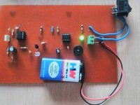
Use BD139 transistor
can i use a dc motor?
sir motors are rotating but ldr doesnt work and transistors are also get heated so whats the problem pls tell me sir??
Nope, it is not related to parallel port or computer. It is a simple line follower robot.
Hello sir is this project related to parallel port car driving and if it is how will I be able to make the car move because I can’t start running behind it to make it stop if I connnect it with the battery directly neither I’m allowed to use Adriano plz reply fast
Yes, you can us BC548
What will happen if i use bc548 instead of bc547. Plz reply fast. I dont have bc 547. And its difficult to find bc 547.
It is not good to control the speed using resistors. You can try using BC107, it will support more current.
What motor specs did you use?
I don’t know because the kit I bought didn’t gave specs for the motors. It is working but it is too fast. I tried putting resistors to slow it down but it is still too fast (with 2N2222A)
Choose depending on the power requirement. What is the current required for that motor ?
Which transistor would you use for a 3-6V DC hobby toy motor? I think a 2N2222 would work but I would like your opinion.
You can use a preset. For IC image just search on google.
Sir can u send me the image of the potentiometer and the IC to be used in this……….
Don’t you connected motor in series with transistor ?
If you motor requires more current, replace the transistors with one having higher current rating.
Sir i have given 12v , both the transistors got blown and with 9 v its not working properly and the circuit is okk.
What should i do
Just check the both motors individually by providing light to each LDR one by one.
Sorry, we don’t have any more photographs. Please check other comments. Some peoples posted the photographs of completed project.
sir, one motor is working both on black and white path… i hv checked all connections. they r right.. and also try to change the sensitivity but the motor is working both on black and white path. plz hlp and rply… @lijoppans:disqus
CAN U PLZ SHARE MORE PHOTOGRAPHS OF THIS PROJECT…. i mean how to assemble all things… i din’t understand properly.. plz help
Try debugging each sections manually by providing light..
If it is working, try adjusting the sensitivity of LDR
You should use 9 ~12V motor for above project.
I’ve made a robot path but robots do not follow the black line, how you can help
sir this is 5V motor do we need to connect Voltage regulator 7805 in place of motor in this circuit and then to this motor ??
It is LDR (Light Dependent Resistor).
I am new here, please tell me which part is used as sensor in this ccircuit ??
i am new here !! will you tell me which part is used as a sensor in ckt diagram
1 IC ..
Its connected to the middle terminal of the potentiometer
Sir have you used 1 or two ics
Where do the 2nd leg of op amp connect to? There is an arrowhead there, whats that suppose to mean?
You can use a preset..
send me the pic of the potentiometer used in the robo
sir can u send me pic of potentiometer which is used in it ?
thank you sir can u send me image of potentiometer which is used in…
It is a potentiometer for adjusting the sensitivity ..
sir what is RV1 & RV2
Only 1
how much lm358n should we use
Thanks for the feedback .. 🙂
I completed this line follower.thank you Ligo George.It`s working perfectly.
Sorry, we haven’t any video of above project..
Yes, it should work..
the above diagram is the simplest circuit diagram you’ll find
i am new to this i want simple circuit diagram to do line follower robot or video how to do line follower by stepby step
if i use 12V with 1800mah,will it work? no any harm to the circuit?
It will depend on how much time your robot should work…
mAh => milliampere per hour…
eg : if the battery is 1.2Ah, 12V >> it can give 1.2A current with 12V for 1 hour…
if you are drawing 600mA it will work for 2 hours..
Yes, it should work… limited by the total weight..
what kind of mAh power should i used to run this motors with 9V?
If i use this motor,it will work know.
Your motors should not have enough torque.. You should use geared dc motors.
yes,i used dvd rom motors.and 9v battery.
Yes you can use BC107..
Are you using 12V dc motor with 9V supply.
That 9v battery might not be able to drive DC Motors, you should use a good battery having more Ah capacity.
you are saying,we can use BC107 transistor for the BC547 transistor know?
Yes, only one IC is required…
do we need only one LM358N IC know?
sir i have checked my circuit , several times .. but still it is not working. help me !
Yes it will but… it can’t be used as a Line tracer..
sir .. will this circuit work, if i use only half of the circuit that is .. if i want to run only one motor using ldr.. will this circuit work ?
It should work.. try replacing the LDR..
Thank you for your reply, I’m still stuck with the same problem, I have triple checked the circuit and tried changing the IC and the BC547, the pot doesn’t have any effect(I’ve tried changing the pot also). The motor which is controlled by 5,6,7 pin of the ic, works like charm.. but the motor controlled by the pin 1,2,3 doesn.t work at all… please help!!
Try adjusting the sensitivity using preset..
Try adjusting sensitivity using presets..
You can use two 12V 40RPM geared dc motors..
Sir, i have a problem, my left motor is working perfectly fine but right side motor is working both in light and dark. I have checked the circuit many times there is no fault in the circuit.. please help me..
sir motors are running both in light and dark. please guide me
sir can you please tell me what current and voltage, motors required to run ?
It is a difficult question to answer..
Choose resistors depending on the required resistance value and power rating..
choose transistors using max voltage, current and current gain required. .
Each components has its own way..
Use IR sensor pair.. you can use comparators with presets to adjust sensitivity of each sensor..
Output of each comparator (digital o/p) can be connected to pic..
Geared DC motor has gears attached to simple DC motor to increase torque..
Select the color of LED depending on the surface color .. or use white led..
I have a small question.how can we select the components for our projects..I mean where to start..how to select those resistors and specific transistors and all the others…
hello,
say me about motors,,what is difference between simple DC motor and geared DC motor? what effect it will make if i use simple DC motor? Also describe, which LED,LDR pair will be better for sensor? It will be great if you will show me circuit analysis (i mean how values of resistance and current detail)
thanks
how can I do this robot with PIC16f877a ,,,, shall i connect the LDR to the analog pins ,,or as pull up resistor ,,please help me with the code by micro c pro
Also I want to make a robot with ultrasonic sensor I found the interface with microcontroller what should I do to make this robot ,, thank you sir
Just interchange the + and – pins of opamp comparator.
hi, what should I do if I want to make the robot to follow a white line on a black surface
reduce the base resistor of transistors..
it shows output on led but fluctuate in relay motor combination.
i think there is the problem of current. but i cant figure out what exactly going on there.. what about transistor ???
What about the output of opamps… does it correct?
Thanks, i have checked my relay module separately it work perfect. but when it connected to the op amp then shows problem.
any other solution???
can u tell me which is perfect transistor combination for darlington pair which gives me more than 200ma current rather than bc574.
I think you might have some problem with one relay or darlington pair… check it by turning on separately..
i have connected darlington pair at the o/p of both opamp and to which i have connected relay and motor but when both o/p is high my one relay goes off so the motor. please suggest the solution..
thank you.
Your motor might require more current, than BC547 transistor can safely handle…
Replace BC547 transistors with BC107..
very easy circuit
nice yaar
great yaar……….