Voltmeter and Ammeter using PIC Microcontroller
Voltmeter and Ammeter can be easily made using PIC Microcontroller having ADC (Analog to Digital Converter). I am using PIC16F877A and the result is displayed on an LCD Display. PIC16F877A is enough if you do this project only for testing purposes. I suggest to use PIC with low pin numbers and multiplexed 7 segment display if you wish to use this as your measuring instrument.
Prerequisite
If you don’t know the basis of PIC ADC and LCD Interfacing please read the following articles.
ADC Calculation
ADC module of PIC Microcontroller converts the Signals on its analog pin to 10 bit binary data and it has software selectable high and low voltage reference input to some combination of VDD, VSS, RA2 and RA3. The analog input to PIC is limited to VSS and VDD voltages (0 – 5V) of PIC.
This circuit is designed to measure 0 to 30V. So we will map 0 to 30V to 0 to 5V by using a voltage divider. Current through a circuit can be measured by introducing a 1 ohm resistor and measuring the voltage across it. To minimize the path resistance we will use .47 ohm special resistor with fuse (shown in figure) and current is calculated. Voltage and Current Sampling circuit is shown below. When the Input voltage is 30V (max) the voltage across 20K ohm resistor becomes 5V which is feedback to the analog pin RA2 of the PIC Microcontroller.
 The voltage across .47 ohm resistor is also feedback to the analog pin RA3 via 100K ohm resistor. 5.1V Zener Diode is added in parallel to these analog input pins to protect PIC from over voltages.
The ADC module of PIC converts analog input to 10 bit digital number. We want to convert this digital to corresponding voltage in decimal.
- 0v = 0 0 0 0
- 5v = 1 1 1 1
Resolution = (Vref+ – Vref-)/(1024-1) (as it is 10 bit ADC)
= 5/1023
= 4.887 mV
Thus it means that for a change in 4.887mV, the binary output changes by 1.
So voltage input to the analog pin of PIC can be calculated as follows…
v = ADC_Read(2);  // ADC value of channel 2 (voltage)
i = ADC_Read(3);  // ADC value of channel 3 (current)
V = v*4.89;       // Converting ADC value to mV
I = i*4.89;       // Converting ADC value to mV
By using values V and I we can calculate the Input Voltage and Current across the Load (Connected across Output terminals).
Voltage across 20K resistor = V
Current through 20K = V/20K
Input Voltage = Current through 20K * 120K (Current flowing to PIC can be neglected)
Thus,
V = (V/20)*120;
Voltage across 0.47 ohm resistor = V
Current through Load = Current through 0.47 ohm resistor = V/0.47
Thus,
I = I/0.47;
To display the results in LCD Display we need to convert these readings into string, we use the user defined function look() for it. It converts each digit in the reading to corresponding character (see the source code).
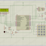
Circuit Diagram
Note: VDD and VSS of the pic microcontroller is not shown in the circuit diagram. VDD should be connected to +5V and VSS to GND.
MikroC Code
// LCD module connections
sbit LCD_RS at RB5_bit;
sbit LCD_EN at RB7_bit;
sbit LCD_D4 at RC4_bit;
sbit LCD_D5 at RC5_bit;
sbit LCD_D6 at RC6_bit;
sbit LCD_D7 at RC7_bit;

sbit LCD_RS_Direction at TRISB5_bit;
sbit LCD_EN_Direction at TRISB7_bit;
sbit LCD_D4_Direction at TRISC4_bit;
sbit LCD_D5_Direction at TRISC5_bit;
sbit LCD_D6_Direction at TRISC6_bit;
sbit LCD_D7_Direction at TRISC7_bit;
// End LCD module connections

char look(int a)
{
  switch(a)
  {
    case 0:
      return '0';
    case 1:
      return '1';
    case 2:
      return '2';
    case 3:
      return '3';
    case 4:
      return '4';
    case 5:
      return '5';
    case 6:
      return '6';
    case 7:
      return '7';
    case 8:
      return '8';
    case 9:
      return '9';
    default:
      return '.';
  }
}

void main()
{
  unsigned int v,vp,ip,i;
  char *volt = "00.0";
  char *current = "0.00";
  CMCON = 0x07;
  TRISA = 0xFF;
  ADCON1 = 0x00;
  Lcd_Init();
  Lcd_Cmd(_LCD_CLEAR);
  Lcd_Cmd(_LCD_CURSOR_OFF);

  do
  {
    v = ADC_Read(2);
    i = ADC_Read(3);
    i = (i*4.89)/0.47;
    v = ((v*4.89)/20)*120;
    if(v!=vp || i!=ip )
      Lcd_Cmd(_LCD_CLEAR);
    vp = v;
    ip = i;
    volt[0] = look(v/10000);
    volt[1] = look((v/1000)%10);
    volt[3] = look((v/100)%10);
    Lcd_Out(1,1,"Voltage = ");
    Lcd_Out(1,11,volt);
    Lcd_Out(1,16,"V");

    current[0] = look(i/1000);
    current[2] = look((i/100)%10);
    current[3] = look((i/10)%10);
    Lcd_Out(2,1,"Current = ");
    Lcd_Out(2,11,current);
    Lcd_Out(2,16,"A");
    Delay_ms(250);
  } while(1);
}
You may also use IntToStr() to convert integer to string
Download Here
You can download the hex file, MikroC source code, Proteus files etc here…




Above section just converting integer to corresponding character.
{
switch(a)
{
case 0:
return ‘0’;
case 1:
return ‘1’;
case 2:
return ‘2’;
case 3:
return ‘3’;
case 4:
return ‘4’;
case 5:
return ‘5’;
case 6:
return ‘6’;
case 7:
return ‘7’;
case 8:
return ‘8’;
case 9:
return ‘9’;
default:
return ‘.’;
}
sir would you kindly clear me why above code is necessary for the project
Its always showing 0 volt and 0 amp
Plz help
what changes i have to do in it
Hi, i am using same circuit but amps is zero only, how i can increase or decrease amps,
voltage is correctly showing 30V dc,
i have also applied dc ammeter , it is also showing 0.00 value,
proteous scren shot attached, kindly see. https://uploads.disquscdn.com/images/137bbd5811ab6acba1b5830fd5e47e90f07656c18befc36106e473662d4c2086.jpg
Hi, i am using same circuit but amps is zero only, how i can increase or decrease amps,
voltage is correctly showing 30V dc,
i have also applied dc ammeter , it is also showing 0.00 value,
Hi Ligo sir,
I am currently working with the wireless mobile charging. Will this idea work for changing Current and Voltages, and why did you used a 5 v battery for the Vpp input…???
For example 10.5 volt detection
Dear sir,could you please support me to know how select specific voltage to take a particular action thank you
Hello, Can you tell me a store where I find the resistor R4 0,47? What is the link to datasheet?
how can i run it plz ? how to do a simple simulation of this project , i’m new to this ! SOS
Hello Ligo, if i want to monitoring just the voltage can i delete the 0.47 resistor and 100k ?
Cheers
You can use a 10K preset there.
What is ATS ?? You can use our forums ( https://electrosome.com/forums/ ) if your query is out of the scope of above article.
Hey mate,
Can you please tell me what value is RV1 exactly?
https://uploads.disquscdn.com/images/8abf2d035db4c68e245ecbf90b1255187963014ef9a5d93045c6f70b36df511d.jpg
This is the circuit I’m using for the ATS voltage measurements.
Hello I’m a newbie in the world of PIC, and coding. I’m building a an ATS with vtage and current measurements. I have a simple diagram and when I try to implement the code all I see is a light on the LCD screen. I’m using Proteus 8, and mikroC. Please help me with any working diagram and code that is working.
Check my design.
hello sir
where should we provide the input source while running simultion on proteus
Sorry, I don’t understand the problem.
Make sure that the value of resistor is accurate for all currents. Try debugging in the program.
for high currents you need to use high wattage resistance.
Hi sir,
can you explain to me what the R3 resistor is good for? Is it just for current flow reduction into the proc?
Does it have any effect on the current measurement (along with 0.47R)?
It seems to measure well, but…
I changed the 0,47R resistor for 0.1R (with 3A load it would become quite hot (5W type) and I would like to reduce the heat). I have also changed the line “i = (i*4.89)/0.47” –> i = (i*4.89)/0.1. Proteus works fine, it shows correct numbers, but the hardware does not, unfortunately.
With 12V and 100R resistor as a load it should show 0,12A (but it displays 0,09A), however, with 10R load it displays 1,35A (it should be 1,2A)… it seems the error grows with larger load and descends with lower load… ??? When I put 0,47R back, it works fine… Do you have any idea ? Thanks a lot… M.
only DC currents
Dear Mr. Mark,
Sorry for the delay in reply. I will ready comments only when I get free time.
Yes, I can help you regarding that. I have good knowledge in both hardware and software aspects of that project. You can write to me : [email protected]
If you are planning to measure AC currents, use a current transformer.
Mr Ligo George can you help me
Voltmeter and Ammeter using PIC Microcontroller but I am going to use online monitoring website to displayed the result instead LCD Display. Do you have any idea how create it? I am very thankful for your help
can i use a shunt of 200A/75mV in place of resistor of 0.47R and change the range of measure ? and how can implement this?
No, It seems like some logic mistake only.
Are you using AC ? The above project is for measuring DC voltages.
Today i worked on this project. First i want to thank you. I increased the amperes to 40 and it reads correctly in the proteus simulation. Used voltage divider on this circuit, setted the voltage formula x240, it is ok with 60 Volt. But when i use 1/3 divider and set the voltage formula to x 360, LCD shows me half of the real voltage.. So there is always half voltage at the screen after 60 V.
i’m using cracked MikroC Pro.. May be because of it ?
HI you have an idea on ph metre using microcontroller pic16f877A
and send to me program in mikroc
Just use a pic microcontroller programmer.
Above code is for MikroC Pro.. not for MPLAB.
ligo how to program this code into my picf877a?
can you teach me to build this code using mplab.ide? i have try but its not success
You can multiply it before the matrix.
You can increase the delay in the while loop.
I am unable to multiply v & i because they in matrix form. Can u help me to multiply by converting them first to integer? I cant convert it to int. It gives me an error
sir can we use 16F876A in place of 16F877A
Yes, it is. Wattage depend on the maximum current required, I*I*R.
hi, is it measure both voltage and current?
What is the 0.47 Resistor Wattage?
You can simply convert variables i & v to string using IntToStr();
char temp[7];
IntToStr(i,temp);
Thank you Mr.Ligo
could you please help me and edit the code to be able with using FloatToStr()
I tried to much, but still NOT working , I really need your help.
Thank you
hello sir, what is the result that displayed on ur lcd? i’ve got current = 0.00 and voltage = 00.0 . what should i do to change the value? hope for ur answer. tanks sir
For finding DC wattage you can simply multiply voltage and current.
Dear Ligo please how can integrate wattmeter to this project and the cod
Hello George,
nice circuit you have built here 🙂 i’m trying to build one myself…still learning some details… can you tell me what is the maximum current intensity shown on the ldc?
ok thank you
Adjust the current constant to make it correct….
You mean AC or DC ?
If it is DC you may use proper voltage dividing resistors for that.. but it is recommended to use proper isolation as you are playing with HIGH voltages.
What do you mean ?
the current that indicated this is not true because it is high help
hi 🙂
what i can do when i like use 220v en place of 30v ?
who i can search a power?
It is to extract each digit and to convert it to character…
Current format : “0.00”
Voltage format : “00.0”
why you use :
volt[0] = look(v/10000);
volt[1] = look((v/1000)%10);
volt[3] = look((v/100)%10);
why %10 !!
why in current you used [0] [2] [3] And in voltage you used [0[2][3]
There is no adcon0 above.. only adcon1..
Just change the voltage dividing resistor values .. and constants..
hell sir
In this prog what configration of adcon0 register
Hi,
hare volt meter max 30v. but how can i calculate for 100V … can you help me..
Yes, you may use it by disabling the LCD by providing LOW to Enable pin of LCD.
But the best solution is to use serial communication UART.
1. Make sure that LCD connections are correct and PIC program is running.
2. Try adjusting the contrast potentiometer.
hello i’ve built it(although i used a pic16f88) and it works like a charm and now i would like to send the results through parallel transmission to a second pic robot brain. my problem is that i have not enough pins can i use the pins that interface with the lcd to also be used in the parallel transmission?
thanks a lot in advance
hi ligo can you help me. i’ve used your circuit and code above. the problem is when connected to the lcd display it only displays bar on the lcd thanks i hope you can help me
I saw it.. even though it should work…
See the pic
It should work without any problem.
Hi,
volt and amps meter you are using ic PIC16F877A , when i use pic16f73 . not working. showing wrong voltage..
whats the problem?
Code:
// LCD module connections
sbit LCD_RS at RB2_bit;
sbit LCD_EN at RB3_bit;
sbit LCD_D4 at RB4_bit;
sbit LCD_D5 at RB5_bit;
sbit LCD_D6 at RB6_bit;
sbit LCD_D7 at RB7_bit;
sbit LCD_RS_Direction at TRISB2_bit;
sbit LCD_EN_Direction at TRISB3_bit;
sbit LCD_D4_Direction at TRISB4_bit;
sbit LCD_D5_Direction at TRISB5_bit;
sbit LCD_D6_Direction at TRISB6_bit;
sbit LCD_D7_Direction at TRISB7_bit;
// End LCD module connections
char look(int a)
{
switch(a)
{
case 0:
return ‘0’;
case 1:
return ‘1’;
case 2:
return ‘2’;
case 3:
return ‘3’;
case 4:
return ‘4’;
case 5:
return ‘5’;
case 6:
return ‘6’;
case 7:
return ‘7’;
case 8:
return ‘8’;
case 9:
return ‘9’;
default:
return ‘.’;
}
}
void main()
{
unsigned int v,vp,ip,i;
char *volt = “00.0”;
char *current = “0.00”;
TRISA = 0xFF;
TRISB = 0x00; // Battery charing on off port
PORTB = 0x00;
TRISC = 0x00; // Load OUTPUT
PORTC = 0x00;
Lcd_Init();
Lcd_Cmd(_LCD_CLEAR);
Lcd_Cmd(_LCD_CURSOR_OFF);
do
{
ADCON1 = 0x00;
v = ADC_Read(2);
i = ADC_Read(3);
s = ADC_Read(1);
i = (i*4.89)/0.47;
v = ((v*4.89)/20)*120;
s = ((s*4.89)/20)*120;
if(v!=vp || i!=ip )
Lcd_Cmd(_LCD_CLEAR);
vp = v;
ip = i;
volt[0] = look(v/10000);
volt[1] = look((v/1000)%10);
volt[3] = look((v/100)%10);
Lcd_Out(1,1,”Voltage = “);
Lcd_Out(1,11,volt);
Lcd_Out(1,16,”V”);
current[0] = look(i/1000);
current[2] = look((i/100)%10);
current[3] = look((i/10)%10);
Lcd_Out(2,1,”Current = “);
Lcd_Out(2,11,current);
Lcd_Out(2,16,”A”);
Delay_ms(250);
} while(1);
}
Your question haven’t enough details to write the code.
What should be the LED state when the voltage is below 1V and curret is below 1A ?
hmm
How can i controls PORTD0 LED. 11V up PORTD0 Led off, 11v under PORTD0 LED ON.
when amper 1 up PORDT0 LED ON. under PORTD0 LED off.
how to write like this coding. can u help me?
Both functions controls LED connected to PORTD0… .
So function 2 will always override function 1 as per your coding..
Thank u for replay.
// function 1 when volt 11 under i want PORTD0 LED on.
when i remove code // function 2, this time // function 1 PORTD0 led is working,
when add // function 2 this time //function 1 PORTD0 not working. but i don’t understand why not working.
12F675 is an 8 pin ic right ?
There will be 6 pins for I/O operations if we use internal oscillator and MCLR as IO..
But you need those 6 pins for connecting LCD…
Then how will you measure voltage/current ?
You may use serial LCD to save pins.. but it is better to use a microcontroller having more pins..
hi ligo,
i’ve read through most of your posts and their comments and i like how u respond to quenstions quickly in the comments section. it’s good for learning. keep it up.
i’m building a power inverter and i think i can adapter this meter, with some modifications, to my project to display battery voltage, load current and power on 16×2 lcd.
my doubt is the pic i want to use is 12F675, will it work?
As per your coding and comments… PORTD0 LED will be off when v < 11..
Hello sir,
i face problem this code. can u solve this problem
function 2 is working But my problem is function 1 when 11v under PORTD0 led not on always off.
why always off?
// function 1
if(v = 1)
{
PORTD.F0 = 1; // LED off
PORTD.F5 = 1; // LED ON
}
else
{
PORTD.F0 = 0; // Load ON
PORTD.F5 = 0; // Load ON
}
ok 🙂
mm, reading that, I think that degrades more with the offset voltage of the internal op-amp, argh. Thank you
Even if you are using 0.47 ohm resistor… it actual value may vary.. Values each component you are using may vary like this .. So calibrate your program with a standard multimeter by multiplying / adding with a constant… through a series of tests..
Yes it can. .but the accuracy of A/D converter degrades as Vref diverges from VDD.. Following links will help you..
http://www.ti.com/lit/an/slyt331/slyt331.pdf
http://www.ti.com/lit/an/slyt339/slyt339.pdf
http://www.ti.com/lit/an/slyt355/slyt355.pdf
im sorry , i meant to say in series. I have used a 1watt .47ohm resistor,to measure the current .Do u think this might be the issue.
im using 6 leds in series =19.8V 150mA(If=150mA for each led)
the voltage and current is provided by the DC source 19.8V 150mA. When i connect the ammeter in series with the led strip it reads 160mA whereas on the LCD it reads .28 A . I tried to make changes in code.But nothing helps.Kindly help.
Hi, what if, for example, my Vref+ is 20mV and my Vref- is 10 mV and I use a 10 bits ADC, does the chip can read voltages in order of microvolts? I can’t find it in datasheet. Thanks for the help.
I don’t understand the problem.. .please troubleshoot it yourself… it is very simple…
i mean when 10volt up and down always led on.
if(v > 10)
{
PORTD.F0 = 1;
Delay_ms(10);
}
use else section to turn off the led.
sir, is not working..
code:
if(v == 10)
{
PORTD.F0 = 1;
}
when i change like this led on but problem is always led on.
if(v > 10)
{
PORTD.F0 = 1;
Delay_ms(10);
}
Don’t use 1N4007 instead of Zener Diode…. Use can use a 5.1V Zener Diode there… otherwise leave it .. don’t use any diodes..
Current Across LED ??
Current measurement should be done in series with LED..
Just measure the actual current using ammeter … and let me know both values..
Try after reading the ADC section of PIC 16C73B..
You might want to make some changes in ADC Control registers..
Logic is correct.. .but it is very difficult to make the voltage exact 10V… try making some tolerance… like…
9.8<v<10.2
hi lijo, i have tried the same circuit in order to measure voltage and current across leds, the voltage is working perfect, wheras im facing issue while displaying current.The current value is always flickering and hardly shows the right current value, could you please suggest a fix.
not working sir,,
hi lijo, i have tried the same circuit in order to measure voltage and current across leds, the voltage is working perfect, wheras im facing issue while displaying current.The current value is always flickering and hardly shows the right current value, could you please suggest a fix. im using in4007 instead if in4733A,is it ok?
hi lijo, i have tried the same circuit in order to measure voltage and current across leds, the voltage is working perfect, wheras im facing issue while displaying current.The current value is always flickering and hardly shows the right current value, could you please suggest a fix.
Hi logo
you are using pic16f877a Voltmeter and Ammeter. when i use ic pic16C73B volt and ammeter not perfect working.
what’s problem i don’t understand. i just change ic…
I attach picture file.
Hi logo,,
It’s workinggggg….
HI, is not working led on off when 10 volt led on, 10 volt up led off here is code. can u tell me what the problem.
// LCD module connections
sbit LCD_RS at RB5_bit;
sbit LCD_EN at RB7_bit;
sbit LCD_D4 at RC4_bit;
sbit LCD_D5 at RC5_bit;
sbit LCD_D6 at RC6_bit;
sbit LCD_D7 at RC7_bit;
sbit LCD_RS_Direction at TRISB5_bit;
sbit LCD_EN_Direction at TRISB7_bit;
sbit LCD_D4_Direction at TRISC4_bit;
sbit LCD_D5_Direction at TRISC5_bit;
sbit LCD_D6_Direction at TRISC6_bit;
sbit LCD_D7_Direction at TRISC7_bit;
// End LCD module connections
char look(int a)
{
switch(a)
{
case 0:
return ‘0’;
case 1:
return ‘1’;
case 2:
return ‘2’;
case 3:
return ‘3’;
case 4:
return ‘4’;
case 5:
return ‘5’;
case 6:
return ‘6’;
case 7:
return ‘7’;
case 8:
return ‘8’;
case 9:
return ‘9’;
default:
return ‘.’;
}
}
void main()
{
unsigned int v,vp,ip,i;
char *volt = “00.0”;
char *current = “0.00”;
TRISA = 0xFF;
TRISD.F0 = 0;
PORTD.F0 = 0;
Lcd_Init();
Lcd_Cmd(_LCD_CLEAR);
Lcd_Cmd(_LCD_CURSOR_OFF);
do
{
ADCON1 = 0x00;
v = ADC_Read(2);
i = ADC_Read(3);
i = (i*4.89)/0.47;
v = ((v*4.89)/20)*120;
if(v!=vp || i!=ip )
Lcd_Cmd(_LCD_CLEAR);
vp = v;
ip = i;
volt[0] = look(v/10000);
volt[1] = look((v/1000)%10);
volt[3] = look((v/100)%10);
Lcd_Out(1,1,”Voltage = “);
Lcd_Out(1,11,volt);
Lcd_Out(1,16,”V”);
current[0] = look(i/1000);
current[2] = look((i/100)%10);
current[3] = look((i/10)%10);
Lcd_Out(2,1,”Current = “);
Lcd_Out(2,11,current);
Lcd_Out(2,16,”A”);
Delay_ms(250);
//——led on off—————–
if(v == 10)
{
PORTD.F0 = 1;
}
else if(v > 10)
{
PORTD.F0 = 0;
}
} while(1);
}
if(v == 10)
//LED ON
else if(v > 10)
//LED OFF
just do like this..
if(v == 10)
PORTX.Fy = 1; // LED ON
Hi logo. I want add led in voltmeter . How write code . when voltmeter show 10 volt Led on. When 10volt up led off.
Hello sir,
How to coding . When meter volt show 10volt led on.
Hello,
It is described in the above article itself..
Hello, your doubt is off the topic.. please use our forums ( http://electrosome.com/forums ) for such doubts..
Hi,this line ( i = (i*4.89)/0.47; V = (V/20)*120; ) How to find for amps 0.47 this number , and for volt this number 20,120 . i don’t understand can u explain me.
Hello Mr Ligo
I try to make a project and I have some difficulties…
Here is my code..
// LCD module
sbit LCD_RS at RD2_bit;
sbit LCD_EN at RD3_bit;
sbit LCD_D4 at RD4_bit;
sbit LCD_D5 at RD5_bit;
sbit LCD_D6 at RD6_bit;
sbit LCD_D7 at RD7_bit;
//End of LCD Module
//LCD pin direction
sbit LCD_RS_Direction at TRISD2_bit;
sbit LCD_EN_Direction at TRISD3_bit;
sbit LCD_D4_Direction at TRISD4_bit;
sbit LCD_D5_Direction at TRISD5_bit;
sbit LCD_D6_Direction at TRISD6_bit;
sbit LCD_D7_Direction at TRISD7_bit;
// End LCD module connections
char look(int a)
{
switch(a)
{
case 0:
return ‘0’;
case 1:
return ‘1’;
case 2:
return ‘2’;
case 3:
return ‘3’;
case 4:
return ‘4’;
case 5:
return ‘5’;
case 6:
return ‘6’;
case 7:
return ‘7’;
case 8:
return ‘8’;
case 9:
return ‘9’;
default:
return ‘.’;
}
}
void main()
{
unsigned int v,v1;
int x,j ;
char *volt = “00.0”;
char *volt1 = “00.0”;
TRISA = 0xFF; //PORTA is Input
TRISE.F0 = 0xFF; //RE0 is Input
TRISE.F1 = 0xFF; //RE1 is Input
TRISB.F0 = 0; //RB0 is Output
TRISB.F1 = 0; //RB1 is Output
TRISC.F2 = 0; //RC2 is Output
Lcd_Init();
Lcd_Cmd(_LCD_CLEAR);
Lcd_Cmd(_LCD_TURN_ON);
Lcd_Cmd(_LCD_CURSOR_OFF);
PWM1_Init(400); //PWM duty cycle 75%
PWM1_Start();
PWM1_Set_Duty(192);
do
{
Lcd_out(1,1,”TASK No3″);
if (PORTE.F1==1){
Lcd_out(3,-3,”OVERFLOW”);
}
ADCON1 = 0x00;
v = ADC_Read(2);
v1 = ADC_Read(3);
v1 = ((v1*4.89)/20)*120;
v = ((v*4.89)/20)*120;
volt[0] = look(v/10000);
volt[1] = look((v/1000)%10);
volt[3] = look((v/100)%10);
Lcd_Out(3,-3,”Voltage = “);
Lcd_Out(3,8,volt);
Lcd_Out(3,12,”V”);
volt1[0] = look(v1/10000);
volt1[1] = look((v1/1000)%10);
volt1[3] = look((v1/100)%10);
Lcd_Out(4,-3,”Voltage1 = “);
Lcd_Out(4,8,volt1);
Lcd_Out(4,12,”V”);
Delay_ms(250);
PORTB = 0;
Lcd_Out(2,1, “00011000”);
delay_ms(200);
PORTB = 1;
Lcd_Out(2,1, “00100100”);
delay_ms(200);
PORTB = 2;
Lcd_Out(2,1, “01000010”);
delay_ms(200);
PORTB = 3;
Lcd_Out(2,1, “10000001”);
delay_ms(200);
PORTB = 2;
Lcd_Out(2,1, “01000010”);
delay_ms(200);
PORTB = 1;
Lcd_Out(2,1, “00100100”);
delay_ms(1);
} while(1);
}
I use PIC16F877A and proteus for simulation.
My problem is in this point of my code:
if (PORTE.F1==1){
Lcd_out(3,-3,”OVERFLOW”);
}
My PIC do not write OVERFLOW and simply read the analog value…
Also, when I put a motor with PWM technique the hole program became very slow
PWM1_Init(400); //PWM duty cycle 75%
PWM1_Start();
PWM1_Set_Duty(192);
Thanks for your time…!
Yes, you are right… but it will take some time to list all commonly used components and modules…. We need to buy all items before listing from wholesale dealers.. It needs time and money…
Thanks… 🙂
1n4733a ഒരിടത്തും ഇല്ല. tutorial പോസ്റ്റ് ചെയ്യുന്നതോടൊപ്പം അതിനാവശ്യമായ എല്ലാ കംപോനെന്റ്സും സ്റ്റോറിൽ ഇട്ടാൽ വളരെ നന്നായിരിക്കും.
It will be less than 300mA.. to find actual current you should add currents of each components used..
LCD + LCD Back LIGHT + PIC + etc..
How much current will consume this circuit?
Yes …
You may make some changes in the Voltage Divider part and program.. .. to change 0 -30 range to 0 – 15V range.
Sure…
Thanks for the feedback…
We need some time to make our store better… as we are on the starting stage..
Can we use this circuit for continues(24*7) voltage measurement of a 12v lead acid battery?
Add more products to your store.. (Servos, steppers, diy cnc …)
Actually, I didn’t get what your are asking… I hope that 3 LEDs are connected in series so total voltage drop = 3.3 + 3.3 + 3.3 = 9.9V …. You can connect voltage divider (R1 + R2) parallel to these LEDs …
Then you can measure the voltage as done in above project… … You can download the code above.
hi, im trying to measure voltage across an led ,by using 2 resistors in series like divider and feeding output to adc,each led takes 3.3v,now suppose i use 3 leds i need my lcd to display voltage as 9.9,could you please suggest me some solutions with respect to coding.,i am using adc, with an input of 9.9v,im getting drop of 1v acrsoss led,and adc value of 200,
No, the circuit is correct. You should connect a load in the output section otherwise no current will flow through 0.47 ohm resistor.
Hi,George,
Nice project ,and i am try to do this myself,but i have one doubt and two problem to resolve,hope you will help me.
in your schematic you have grounded both end of the resistor 0.47 and serially connected a resistor 100k and put it to the microcontroller is it ok?
because this configuration did not give me the current reading,but when i ungrounded the one end of the resistor 0.47 and one end of resistor 100k connected with positive terminal of input voltage it will show the current.
next,voltage reading after decimal point are highly fluctuate how can i made it stable??
next,I want to take this reading voltage as well as current into PC through serial port and plot a real time graph can you please help me out to do this,
Thakns in advance. 🙂
Better to try in the real hardware…
You may try using voltage sources and resistors in the proteus..
Hi, this is an excellent example. I have a very newbie question though…I got the simulator running in Proteus but I don’t see any amps or volts on the LCD, it prints out 0.00 for both values. Now I read from all the comments that I need to add a load. So I have 2 questions how do I specify the voltage and the load on the existing circuit?
Just change the microcontroller in mikroc pro project settings and in proteus..
It will workk
i couldn’t find pic16f877A i using pic16f877 20/p if i specify it in microC and proteus it should still work? the pin layout practically the same
hello, i cant find anywhere to buy 1N4733A diodes what other diodes that can fit here?
hii,,
I can t able to read 5 adc ports at the same time…..
I can able to read the values of 3 adc ports and displayed in lcd perfecty….help….
hello sir, measuring voltage was very helpful.i am using 18f4550 and coding in mikroc. i would like to know if there is anyway that i can measure frequency using zcd or convert it to voltage. if there is anyway pls help me. thanks in advance.
hi… how to create assembly program using PIC16F877A from ldr port A to port B stepper motor..?
I can’t correct the error ,please i need a help !
Hello …
i have a problem with my DVM, when i measure a voltage a cross battery , it give a half voltage of battery
Note: i don’t use above circuit , My circuit is attached bellow
You should connect a load .. to flow current..
sir why current does not display at lcd when the program is running in proteus?
You should change the device to 18F14K22 in the MikroC Project settings and Rebuild the program..
can i use pic18f14k22 for this build? or i need to make other hex file if i change mv?
It will work perfectly without that resistor….
It can be used to protect the microcontroller from over voltage/current…..
If the input voltage is above 5.1V .. zener conducts… R3 will limit the current through the zener…
Zener and R3 can be avoided if you are sure about input voltage and current range..
hello sir if you would please explain why the use of Resistor R3? thanks in advance!!
Then there should be anything wrong in your implementation.. . verify the code in the pic memory.. and connections..
By blank I meant that the LCD is powering up , but is all blank , doen’t display anything.
And yes , I did try adjusting the contrast using the Pot , it was working.
According to the code , I should atleast be getting “Voltage = ” and “Current= ” on the LCD , but I get nothing. The LCD just powers up all blank green.
Did you tried adjusting the contrast adjusting potentiometer of LCD??
Sir,
I am trying to program the PIC16F887A using an ICD 2 programmer by simply importing the .hex file in MPLAB IDE and then writing the file to the chip , but my LCD display stays all blank ( all connections made according to the schematic provided ).
Could you suggest a solution?
Would appreciate a ton 🙂
Import means?? You need to just open the .mcppi file with mikroc pro..
If it is not working.. try creating a new project… and copy paste my code..don’t forget to set the microcontroller to 16F877A and clock frequency to 8MHz when you create a new project.
Hi once more… finally got it work !!! 🙂
But I have one more question : I import the *.mpcii file into microC 8 Pro for Pic. I can see the C code. I do NO changes and I build the project. I get 4 warnings of: “search path does not exist (c:users…defs; c:users…usesp16; f:electronicsembeddedvoltmeter; and f:electronicspower supply” – the first 2 dirs ARE there, the 2nd two not – I dont have F drive !). But the build is compiled successfully.
I have a new hex file and import the design into proteus 8 pro where the new hex is assigned to the PIC. But it doesn´t work – the display shows blinking letter V only (like Volts). I have many warnings of one kind repeatedly occurring – “PIC16CORE – PC=0x0421 Indirect write of 0x30 to address 0x0000 is itself an indirect write”.
My hex is 70 bytes shorter and 35 words shorter than yours. Just mentioning once more – I do NO changes to your C code !!
If I upload your hex, it works fine.
What am I doing wrong ??? Any settings anywhere ???
Thanks once more…:-)
Just use your logic.. .or use mikroc is built in conversion funcitons like IntToStr() or FloatToStr() …
Gregory
Hi Sir. How would you eliminate the leading zero when the voltage or current displayed is less than 1? For example: 250mA as displayed 0.25A is changed to .25A or 450mV as displayed 0.45V is changed to to .45V
You should use low value resistor.. which is able to withstand 70 amps…. I haven’t any experience with such high current.. try searching on google…
I thinks that it is better to use current transformer instead of resistor..
Hello Sir, thank you for all of your help! I would like to measure up to 70 amps, what kind of resistor would I need? Would anything else need
to be changed in the circuit? Thanks!
Usually we can write hex file to pic… just by selecting the microcontroller in programmer software….
Sorry, I have no idea about your programmer….. try searching on google..
Yep, I AM using 16F877A chip and it IS properly selected in my programmer [checked several times]. How about the fuses ? Do I have them set well ?
Thanks anyway… 🙂
Sorry, I am not familiar with your programmer..
Verify that you are using PIC 16F877A and it is selected properly in your programmer settings..
Note that PIC 16F877 and PIC 16F877A are different microcontrollers..
Hi Sir,
I’ve built this ammeter exactly as you show here on this website. However, after connecting it to Vdd [no voltage on input], the display shows no data. [I expected 0V at least. I also checked the trimmer for contrast but in vain].
What fuses should be set when uploading the *.hef file into the chip ???
After burning the PIC I have this error – Fuse Error : 0x2007, Good : 0x3F79, Bad : 0x3F7A.
I am using the K150 chip programmer and the fuses are set like this : WDT-disabled, BODEN-enabled, CPD-disabled, Debug-disabled, Code Protect-disabled, PWRTE-disabled, LVP-disabled, WRT enable-enabled, Oscil-XT
I can read the chip after burn and the code is inside, but verify goes wrong.
ROM ends on line 538 with number 0008 [after it just 3FFF]
Can you help me with this , pleeease ???
Thanks a lot …
Yes… it can work up to 20MHz..
can we use 12mhz for pic16f877a?
select the ädc”in library manager………………..
Sorry for the inconvenience caused..
I think the problem is solved now… It was caused due to our server migration..
Try now..
Download the above program… and go to mikroc project settings…
Then change the device 16F877A to 16F883…. then rebuild the project..
Then you will get the new hex file corresponding to your pic..
sir this download is not starting.i click download button my account is automatically logout. please solve thi problem
hELLO SIR…i want to use pic16F883….you can send a hex.file for this mcu?
[email protected]
It is to convert the integer voltage to corresponding string… You can do it in many simpler ways…
If V = 546000
then volt[0] = ‘5’
volt[1] = ‘4’
volt[2] = ‘.’
volt[3] = ‘6’
so… volt = “54.6”
Sir, would u pls explain this lines
volt[0] = look(v/10000);
volt[1] = look((v/1000)%10);
volt[3] = look((v/100)%10);
The complete project files are shared above..
You can download it above..
Try changing to :
watt[0] = look(w/1000);
watt[1] = look((w/100)%10);
watt[3] = look((w/10)%10);
can you pls send Working C code to this mail id please
[email protected]
thank you 🙂
The Image here.
Sir,
As you say I multiply current and voltage but the output gives weird.
Would you pls check where I have done wrong I pest full code and output
image here. I put i=10; as testing purpose.
// LCD module connections
sbit LCD_RS at RB5_bit;
sbit LCD_EN at RB7_bit;
sbit LCD_D4 at RC4_bit;
sbit LCD_D5 at RC5_bit;
sbit LCD_D6 at RC6_bit;
sbit LCD_D7 at RC7_bit;
sbit LCD_RS_Direction at TRISB5_bit;
sbit LCD_EN_Direction at TRISB7_bit;
sbit LCD_D4_Direction at TRISC4_bit;
sbit LCD_D5_Direction at TRISC5_bit;
sbit LCD_D6_Direction at TRISC6_bit;
sbit LCD_D7_Direction at TRISC7_bit;
// End LCD module connections
char look(int a)
{
switch(a)
{
case 0:
return ‘0’;
case 1:
return ‘1’;
case 2:
return ‘2’;
case 3:
return ‘3’;
case 4:
return ‘4’;
case 5:
return ‘5’;
case 6:
return ‘6’;
case 7:
return ‘7’;
case 8:
return ‘8’;
case 9:
return ‘9’;
default:
return ‘.’;
}
}
void main()
{
unsigned int v,vp,ip,i,w;
char *volt = “00.0”;
char *current = “0.00”;
char *watt = “00.0”;
TRISA = 0xFF;
Lcd_Init();
Lcd_Cmd(_LCD_CLEAR);
Lcd_Cmd(_LCD_CURSOR_OFF);
do
{
ADCON1 = 0x00;
v = ADC_Read(2);
i =10;// ADC_Read(3);
i = (i*4.89)/0.47;
v = ((v*4.89)/20)*120;
w = v*i;
if(v!=vp || i!=ip )
Lcd_Cmd(_LCD_CLEAR);
vp = v;
ip = i;
volt[0] = look(v/10000);
volt[1] = look((v/1000)%10);
volt[3] = look((v/100)%10);
//Lcd_Out(1,1,”Voltage = “);
Lcd_Out(1,1,volt);
Lcd_Out(1,6,”V”);
current[0] = look(i/1000);
current[2] = look((i/100)%10);
current[3] = look((i/10)%10);
//Lcd_Out(2,1,”Current = “);
Lcd_Out(1,9,current);
Lcd_Out(1,14,”A”);
//Delay_ms(250);
watt[0] = look(w/10000);
watt[1] = look((w/1000)%10);
watt[3] = look((w/100)%10);
Lcd_Out(2,1,watt);
Lcd_Out(2,5,”W”);
} while(1);
}
Sir,
As you say I multiply current and voltage but the output gives weird. Would you pls check where I have done wrong I pest full code and output image here. I put i=10; as testing purpose.
// LCD module connections
sbit LCD_RS at RB5_bit;
sbit LCD_EN at RB7_bit;
sbit LCD_D4 at RC4_bit;
sbit LCD_D5 at RC5_bit;
sbit LCD_D6 at RC6_bit;
sbit LCD_D7 at RC7_bit;
sbit LCD_RS_Direction at TRISB5_bit;
sbit LCD_EN_Direction at TRISB7_bit;
sbit LCD_D4_Direction at TRISC4_bit;
sbit LCD_D5_Direction at TRISC5_bit;
sbit LCD_D6_Direction at TRISC6_bit;
sbit LCD_D7_Direction at TRISC7_bit;
// End LCD module connections
char look(int a)
{
switch(a)
{
case 0:
return ‘0’;
case 1:
return ‘1’;
case 2:
return ‘2’;
case 3:
return ‘3’;
case 4:
return ‘4’;
case 5:
return ‘5’;
case 6:
return ‘6’;
case 7:
return ‘7’;
case 8:
return ‘8’;
case 9:
return ‘9’;
default:
return ‘.’;
}
}
void main()
{
unsigned int v,vp,ip,i,w;
char *volt = “00.0”;
char *current = “0.00”;
char *watt = “00.0”;
TRISA = 0xFF;
Lcd_Init();
Lcd_Cmd(_LCD_CLEAR);
Lcd_Cmd(_LCD_CURSOR_OFF);
do
{
ADCON1 = 0x00;
v = ADC_Read(2);
i =10;// ADC_Read(3);
i = (i*4.89)/0.47;
v = ((v*4.89)/20)*120;
w = v*i;
if(v!=vp || i!=ip )
Lcd_Cmd(_LCD_CLEAR);
vp = v;
ip = i;
volt[0] = look(v/10000);
volt[1] = look((v/1000)%10);
volt[3] = look((v/100)%10);
//Lcd_Out(1,1,”Voltage = “);
Lcd_Out(1,1,volt);
Lcd_Out(1,6,”V”);
current[0] = look(i/1000);
current[2] = look((i/100)%10);
current[3] = look((i/10)%10);
//Lcd_Out(2,1,”Current = “);
Lcd_Out(1,9,current);
Lcd_Out(1,14,”A”);
//Delay_ms(250);
watt[0] = look(w/10000);
watt[1] = look((w/1000)%10);
watt[3] = look((w/100)%10);
Lcd_Out(2,1,watt);
Lcd_Out(2,5,”W”);
} while(1);
}
for a 10bit adc of reference voltages…. 0 and 5V..
INput —- > ADC-Output
0 —-> 0000000000
4.887mV—-> 0000000001
2.5 —-> 0000011111
5V —-> 1111111111
So ADC output is not voltage.. it is the corresponding 10 bit digital value……
You can convert it to any format as per your requirement…… Here for convince .. it is converted to milli volt…..
Read this article carefully..
Try this too..
http://www.electrosome.com/analog-to-digital-converter-pic/
do you have any website or link which could help me understand basic sampling from volttage drop to adc,,,if yes pls provide
is it mandate to always covert into millivolt,can i use the corresponding adc value read as my voltage value and convert it to current and use it….
Yes.. it just converts the 10bit ADC value to corresponding milli volt..
V = v*4.89; // Converting ADC value to mV
SO U MEAN TO SAY THAT 4.89 IS MULTIPLIED JUST TO CONVERT THE VOLTAGE DROP TO MILLIVOLT ???
Thanks for the reply.
Regards
1. Adjust the potential divider network for the required voltage range..
2. Yes.. for measuring AC.. .first convert it to dc.. the ac voltage = dc voltage/squrt(2)
3. Max current depends on the series resistor…here it is 5V/0.47 …
4. Yes you can measure both voltage and current…. In DC, you can measure power by just multiplying current and voltage..
Hello Sir,
This is a wonderful project. But I have some question.
1. If we want to measure voltage higher then 30V (like 300V) what to do?
2. Can we measure both AC and DC volt with this module?
3. What is the max current that can measure by this module?
4. If we can measure both current and voltage, we can find energy by multiplying them and display in LCD. What should be the code for doing so?
Pls discuss.
Best Regards
Sorry, I don’t understand your question…
opamp???
i cant find OP295A can i still use OP295GPZ or in fact, which other op amps can i replace it with
My query is related to pwm- is it possible to switch voltage levels in ton of a same duty cycle i.e. in the on time i want to divide on time of the duty cycle into 3 samples,provide (assign) three different voltages into these 3 samples -is it possible? i am reading the voltage across resistor to adc pin of uC and displaying voltage on scope thru pwm pin.pls help.
thank you ill try this and get back to you..
To measure current through LED, put a 0.47 ohm fusible resistor (power rating depends of the current required for the LED…. give the voltage across that resistor to the ADC input of PIC… as given in the above circuit diagram… Note one thing, if you are using 2 power supplies, both of them should have a common ground.. as given above..
It is very simple to change the hex file…. you just edit the mikroc program by changing the constant andthen Build the project… The new hex file will be generated automatically..
Sir
do I have to change even the hex code, if so can you help me with it also with the program. im such a bad programmer.
Sir
do I hev to change even the hex code for a 0 to 10 V and 4 to 20 mA, if so can you help me with it also with the program. im such a bad programmer.
Just change the voltage divider for sensing voltage and change the constants multiplied with the data read from adc channel..
that’s working really good. but I would also want to know how to display only 0 to 10 V and 4 to 20 mA if you can help me with the program. Thanks in advance.
That code is not completely correct… I think you need to send voltage and current to second pic. .then why you are writing PORTB to UART…?? if so write voltage and current……
hello do you agree with this?
MikroC Code
Transmitter
void main()
{
unsigned int v,vp,ip,i;
TRISA = 0xFF;
PORTB = 0;
do
{
ADCON1 = 0x00;
v = ADC_Read(2);
i = ADC_Read(3);
i = (i*4.89)/0.47;
v = ((v*4.89)/20)*120;
if(v!=vp || i!=ip )
vp = v;
ip = i;
}
while(1);
UART1_Init(9600); // Initialize UART module at 9600bps
Delay_ms(100); // Wait for UART module to stabilize
while (1)
{ // Endless loop
UART1_Write(PORTB); // and send data via UART
Delay_ms(500);
}
}
Receiver
void main()
{
TRISB = 0;
PORTB = 0;
UART1_Init(9600); // Initialize UART module at 9600bps
Delay_ms(100); // Wait for UART module to stabilize
while (1)
{ // Endless loop
if (UART1_Data_Ready())
{ // If data is received,
PORTB = UART1_Read(); // read the received data,
}
}
}
I used 8MHz crystal.. for using 4 MHz you should change it in mikroc project settings and rebuild it… .. and write the new hex file in the pic microcontroller..
Does the proteus simulation worked fine???
iam using 4MHz it is ok or the problem that i found from it help me
hi i have problem the voltmeter dose not give me right reading when the input is 9 the reading is 30.9 when i test it with avometer across 20k its reads 9 but the lcd reads 30.9 … help me
I haven’t checked the datasheet of 16f88………. If it has 2 adc inputs and uart modules.. you can read voltage, current and send it serially to pic 16f628……….
Try this link : http://www.electrosome.com/pic-to-pic-communication-uart/
hello first of all nice work
secondly can you help me with a project of mine?
can i use pic16f88 instead of pic16f877? what changes would i have to make?
how can i have a serial output? i want to send it to another pic16f628.
Nop, but you can convert it to Hi-Tech C by just by replacing ADC functions, lcd functions and some register assigning statements.. See our Hi-Tech C LCD and ADC tutorials..
is there a HI-tech with MPLAB IDE counterpart of this?
You can measure up to 10A, buy you should use should increase the wattage of 0.47 fusible resistor..
Hi great projedt1 I just have one question..what is the max. amp’s. that this circuit can read in this program ?Thanks in advance.
You need a pic programmer to write program to the pic microcontroller… The required software will depend on the programmer you are using..
sir ,
which software using for download the program to pic……
This code is completely working.. This is PIC16F877A not PIC16F877….. What is the error when writing the program??
The code with this report is not working. But in Proteus, Its work well. But I cant Burn the chips. But intime, I can burn other programme to the same chips. That means, the programmer and the chip are good….
Hope your help soon..
It may caused due to many problems.. you just subtract the correction from the output voltage.. like zero correction..
Hi my friend.
Thanks from software and hardware of VM-AM whit PIC16F877A.
I have made it Voltage is shown up correct bt the amps on 12.00V is shown 160mA without load. What did I do wrong.
Best Regards
Yes, you can.. In every ohm meter, resistance is measured by giving a voltage to it..
Is it possible to measure Resistance by simply dividing measured voltage v by measured current i ? I guess the only problem is that the Resistance to be measured must have a voltage across it
Thank you very much!
It is better to decrease that offset through in program…
hi if wont use this module to 230v i can use transformer and low down the voltage dc 5 but where should i change the programmer?
do you have any tutorials about RF modules and compactors?
thank you vary much
OK, thank you young man and have a nice day/
Best Regards
Vanja
The hex file in the above zif folder is 100% working. Now I checked its working in Proteus ISIS. We don’t provide any wrong hex files in this website.
Hi, my friend L George.
Thanks from replay. O yeah the pic is PIC16F877A and hex does not works. Crystal is 8MHz.
My friend I am bad programmer and I do not know to make HEX file, but I am electronic engineer. I do not have any problem to make PCB and I made it. But hex file make me solid problem. Please would you like to send me one time again that hex file.
Best Regards my friend L George and have a nice day.
Vanja
It is the correct hex file… Note the microcontroller is PIC 16F877A not PIC 16F877 ..
Hi my friend.
I have made this very nice VM-AM, but the HEX file is wrong.
Please would you like to send me new hex file.
Best Regards
Vanja
It is compiling fine in my pc… Create a new project and copy paste the code. Then try to compile
..
my email is [email protected] tks
Good evening Thanks very much the friend Ligo George , i tried use too MikroC PRO 5.8.0 but don’ works, if possible you help me i need ready 40V 30A , possible compiler for me , since already thanks very much one more time , have great hug from Brazil.
Elionaldo.´.
Above code is working fine with my compiler. I am using MikroC Pro 5.8.0
I think you are using MikroC…. Use MikroC Pro..
// LCD module connections
sbit LCD_RS at RB5_bit;
sbit LCD_EN at RB7_bit;
sbit LCD_D4 at RC4_bit;
sbit LCD_D5 at RC5_bit;
sbit LCD_D6 at RC6_bit;
sbit LCD_D7 at RC7_bit;
sbit LCD_RS_Direction at TRISB5_bit;
sbit LCD_EN_Direction at TRISB7_bit;
sbit LCD_D4_Direction at TRISC4_bit;
sbit LCD_D5_Direction at TRISC5_bit;
sbit LCD_D6_Direction at TRISC6_bit;
sbit LCD_D7_Direction at TRISC7_bit;
// End LCD module connections
char look(int a)
{
switch(a)
{
case 0:
return ‘0’;
case 1:
return ‘1’;
case 2:
return ‘2’;
case 3:
return ‘3’;
case 4:
return ‘4’;
case 5:
return ‘5’;
case 6:
return ‘6’;
case 7:
return ‘7’;
case 8:
return ‘8’;
case 9:
return ‘9’;
default:
return ‘.’;
}
}
void main()
{
unsigned int v,vp,ip,i;
char *volt = “00.0”;
char *current = “0.00”;
TRISA = 0xFF;
Lcd_Init();
Lcd_Cmd(_LCD_CLEAR);
Lcd_Cmd(_LCD_CURSOR_OFF);
do
{
ADCON1 = 0x00;
v = ADC_Read(2);
i = ADC_Read(3);
i = (i*4.89)/0.235;
v = ((v*4.89)/20)*120;
if(v!=vp || i!=ip )
Lcd_Cmd(_LCD_CLEAR);
vp = v;
ip = i;
volt[0] = look(v/10000);
volt[1] = look((v/1000)%10);
volt[3] = look((v/100)%10);
Lcd_Out(1,1,”Voltage = “);
Lcd_Out(1,11,volt);
Lcd_Out(1,16,”V”);
current[0] = look(i/1000);
current[2] = look((i/100)%10);
current[3] = look((i/10)%10);
Lcd_Out(2,1,”Current = “);
Lcd_Out(2,11,current);
Lcd_Out(2,16,”A”);
Delay_ms(250);
} while(1);
}
error in compiling
2:0 11 ‘;’ excepted but LCD_RS found
2:0 12 Internal error
I need help to on this file i used MikroC 8.2 , i try make it to read Current 20A , since already thanks very much.
Elionaldo.´.
Hi , I have made this great meter but i have i small problem ow he is in my powersupply the suppl is 24 volt and 5 amp and when i have no load the current gives me 150ma the voltage is perfect what can i dot to change is to zero?
I doint now how to change the software is there a way with a resistor or something?
Thank and sorry for my bad english
thanks it works fine !!!!
8Mhz crystal…
It is better to use a separate power supply for this circuit..
Sorry the first question i read under, about the freq. of the crystal 🙂
Wonderfull project i want to make it thanks for it!
I have 2 questions:
a what kind of crystal you use
and can i take the 5v from the same travo or do i use a second supply for the PIC ?
Thanks
use 8Mhz oscillator… connect mclr to VDD…
ignore other settings…
For current you should connect a load in series with 0.47 ohm resistor…
HI there !
when i connect a battery through a pot at the INPUT it shows Volts on the Lcd but not the amps ! so what i am doing wrong !
and kindly tell me the configuration settings i.e
Oscillator , MCLR, PWRT , WDT OFF.
regards
Sorry, i included the proteus isis file in the download.. kindly convert that file to ares..
hello sir
Can you put the pcb files in proteus ares for this ?
thanks
Connect the supply voltage to input side and connect the load to output side..
hello sir.
how I have to connect to measure current??
thank you so much
Yes, this comes under the title PIC 16 analog inputs… as this project uses ADC of PIC 16F877A………. You can download proteus files at the bottom of the article..
thx for this but i have a question. I have a project titled “PIC 16 analog inputs”. That’s the title, i find it vague. So i was wondering if this fits for that category. We also have to use proteus isis 7 professional to simulate. It’s purely educational it doesn’t have to be actually created as hardware. Note : i am new to this domain but i’m a fast learner.
For dsPICs you should use MikroC Pro for dsPIC… google it .. you can download it and its tutorials from mikroelectronica website..
hello sir,
i using dspic33 ,in .C language,and using mikroC debugger. i have coded it but appear error at ” ADC_READ undeclared identifier”..here my code,can u explain the error why the error.hope ur reply soon.
===============================================================
// LCD module connections
sbit LCD_RS at RB5_bit;
sbit LCD_EN at RB6_bit;
sbit LCD_D4 at RB0_bit;
sbit LCD_D5 at RB1_bit;
sbit LCD_D6 at RB2_bit;
sbit LCD_D7 at RB3_bit;
sbit LCD_RS_Direction at TRISB5_bit;
sbit LCD_EN_Direction at TRISB6_bit;
sbit LCD_D4_Direction at TRISB0_bit;
sbit LCD_D5_Direction at TRISB1_bit;
sbit LCD_D6_Direction at TRISB2_bit;
sbit LCD_D7_Direction at TRISB3_bit;
// End LCD module connections
char look(int a)
{
switch(a)
{
case 0:
return ‘0’;
case 1:
return ‘1’;
case 2:
return ‘2’;
case 3:
return ‘3’;
case 4:
return ‘4’;
case 5:
return ‘5’;
case 6:
return ‘6’;
case 7:
return ‘7’;
case 8:
return ‘8’;
case 9:
return ‘9’;
default:
return ‘.’;
}
}
void main()
{
unsigned int v,vp,ip,i;
char *volt = “00.0”;
char *current = “0.00”;
TRISA = 0xFF;
Lcd_Init();
Lcd_Cmd(_LCD_CLEAR);
Lcd_Cmd(_LCD_CURSOR_OFF);
do
{
AD1CON1 = 0x00;
v = ADC_Read(2);
i = ADC_Read(3);
i = (i*4.89)/0.47;
v = ((v*4.89)/20)*120;
if(v!=vp || i!=ip )
Lcd_Cmd(_LCD_CLEAR);
vp = v;
ip = i;
volt[0] = look(v/10000);
volt[1] = look((v/1000)%10);
volt[3] = look((v/100)%10);
Lcd_Out(1,1,”Voltage = “);
Lcd_Out(1,11,volt);
Lcd_Out(1,16,”V”);
current[0] = look(i/1000);
current[2] = look((i/100)%10);
current[3] = look((i/10)%10);
Lcd_Out(2,1,”Current = “);
Lcd_Out(2,11,current);
Lcd_Out(2,16,”A”);
Delay_ms(250);
} while(1);
}
Please refer the datasheet of corresponding pic…… If you want to code in asm, its datasheet will include all its instructions……
hello sir, in my Embedded course project,i must using this dspic33fj128gp802 PIC. so,which code in asm that i need to change..sorry,i’m newbie about this embedded system.hope u can help me figure i out..thanks for ur support
Nop, 0.47 ohm resistor is connected in series with load, so current through it depends on the load resistance…. and the voltage across the 0.47 resistor is given to an analog pin of pic microcontroller..
Hi! can you please explain in depth what resistors R3 and R4 do? For example, if the input voltage is 30volts on the .47ohm resistor, wouldnt that make the current 63 amps?! wouldnt that fry the micro controller?
Nop… because PICs are different…. for using this circuit.. you may modify my program…
I think this mail id is not valid because I can’t sent mails to it..
carl.victor
[email protected]
Your username and mail id?
i did
but still there is no password emailed
Please elaborate the problem……
Go to this link to register : http://www.electrosome.com/wp-login.php?action=register
hello sir, i can’t download the hex file, mikroC and proteus files cause i can’t register
would you help me?
yes, its working fine i forgot to ground both circuits :p
Try after grounding the inputs….
did you change the program?
I mean to say the values display on LCD keep on fluctuating without connecting any measurement…so what could be the reason ?
Could you please elaborate?
What type of voltage and current ??
Hello sir,
i have made this great Digital Meter + Ammeter. But as soon as i finished programming it with my Pickit3 the values of current and voltage are dancing/fluctuating randomly and its not measuring any value… could u tell me what could be the reason ?
After login click on the download link……. or go to this link
http://www.electrosome.com/wp-content/plugins/download-monitor/download.php?id=5
i already registered and login
First Register and then login….
http://www.electrosome.com/wp-login.php?action=register
how to download the hex file, MikroC source code?
That means you understand voltage calculation…………
Current through 0.47ohm resistor is calculated from the voltage across it…..just ohms law…
i did not understand the current calculations
can you please elaborate
thank you
It will work normally…………. Note: The GND of both power supplies should be connected…
what if, I operate Pic MCU with Vss as 5v and Vdd as 10V ???
what if i operate ic MCU with Vss as 5v and Vdd as 10V
You can use 1/4 watt resistors for R1, R2, R3. Better to use resistors of tolerence 1%. After completing the project measure the value of R1 & R2 and change the program accordingly for accurate results..
hello
I am French and would like to get into this project before but I want to know what tolerence in% and W for resistance R1, R2, R3
1% 0,6 W?
thank you
You may use a small value capacitor (0.001uF) parallel to reduce voltage fluctuations ……… Change the +Vref & -Vref according to voltage that to be converted to digital to increase the accuracy of the adc conversion.
I built this circuits and thanks. However, following are my observations:-
1) For higher amp it reads data properly (e.g. higher than 500mA), but for values lower than 50mA it does not show the correct conversion/ reading
2) Also ADC pin reading are not stable and changes upto +/-3 times, where as load/amp has not been changed
3) I also found that PIC ADC cannot read value below 20 mV and if voltage at ADC pin is lower than it shows output 0 (Zero).
4) also lower amp value shows slightly lower and higher amp values show slightly higher
Thanks.
Thanks a lot for your quick response.
I used 8Mhz……you can use 4 or 8 or 20….
I couldn’t find frequency of the crystal X1 used in your circuit. Would youl let me know that ….?
Using PIC microcontroller we will read the voltage across 20K resistor, then the current through it can be calculated by dividing it with 20K…………
Then the input voltage can be calculated easily by multiplying current through 20K ohm resistor * 120K
Current through 20K = V/20K its may false syntax, maybe its I=V/20k
8Mhz……
voltmeter and ammeter can i know the crystal frequency
thx
You may use our new forums………..
ill just add you sir in your facebook and maybe ill send the schematic there because in email it fails. thank you sir!
Ok mail me the circuit diagram, program, Proteus files etc……..i will check it.
sir this is my code in my digital ohmmeter. i hope you can help me with this….
// LCD module connections sbit LCD_RS at RC4_bit; sbit LCD_EN at RC5_bit; sbit LCD_D4 at RC0_bit; sbit LCD_D5 at RC1_bit; sbit LCD_D6 at RC2_bit; sbit LCD_D7 at RC3_bit; sbit LCD_RS_Direction at TRISC4_bit; sbit LCD_EN_Direction at TRISC5_bit; sbit LCD_D4_Direction at TRISC0_bit; sbit LCD_D5_Direction at TRISC1_bit; sbit LCD_D6_Direction at TRISC2_bit; sbit LCD_D7_Direction at TRISC3_bit;// End LCD module connections// Define Messages
void main() { char message1[] = “DIGITAL OHMMETER “; char *temp = “0000000”; unsigned int v,R1,R2,VCC; TRISC = 0; // PORTC All Outputs TRISA = 0b000011; // PORTA All Outputs, Except RA3 and RA2 Lcd_Init(); // Initialize LCD Lcd_Cmd(_LCD_CLEAR); // CLEAR display Lcd_Cmd(_LCD_CURSOR_OFF); // Cursor off Lcd_Out(1,1,message1); // Write message1 in 1st row do { ADCON1 = 0x00; VCC=5000; R1=10000; v = ADC_Read(1); R2=((v*4.89*R1))/VCC-v*4.89; temp[0] = (R2/1000000)+48; // Add 48 to get the ASCII character value temp[1] = ((R2/100000)%10) + 48; temp[2] = ((R2/10000)%10) + 48; temp[3] = ((R2/1000)%10) + 48; temp[4]= ((R2/100)) %10+48; temp[5] = (R2%10)%10 + 48; temp[6] = R2%10 + 48; Lcd_Out(2,7,temp); Delay_ms(400); } while(1); }
we are encountering problems in displaying it in the LCD. because for example our. R1(fixed)=10000 ohms and our R2(to be measured)=5k ohms. in the display it shows only. less than the desired value..
i will send our ckt diagram in your email sir. because we have problems in uploading the image here. thanks sir!
I use those steps for converting integer to string to be displayed in the LCD………….You needn’t bother about it use inbuilt functions of mikroC such as FloatToStr() , IntToStr()
to convert numbers to corresponding string…
can you explain this part sir i get confused with this:
volt[0] = look(v/10000); volt[1] = look((v/1000)%10); volt[3] = look((v/100)%10); Lcd_Out(1,1,”Voltage = “); Lcd_Out(1,11,volt); Lcd_Out(1,16,”V”);
Yes you can put that equation in mikroC…
Note that actual voltage is adc value * 0.00489 …
I used 4.89 to minimize the floating point calculations…..
Declarations are similar to C…
int variable_name;
float var_name;
short var_name;
etc………
sir using this:
VCC=5V
R1=known resistance or(fixed R1)
R2= unknown or to be measured
v= adc value * 4.89
from:
v=(R2*VCC)/(R1+R2)
i will find R2
after rearranging the equation
it will come up like this sir:
R2=(v*R1)/(VCC-V)
so sir. can i directly put this equation in mikroC compiler?
how about the declaration in mikroC sir?. thank you sir!
Circuit is a problem………….
Use a potential divider to find unknown resistance………..
Connect unknown resistance in series with a known resistance………You may change the known resistance according to the range of Unknown resistance to be measured.
Then by reading voltage across unknown resistance we can easily calculate unknown resistance………
In MikroC you can use the same expressions as in C…….
sir we dont have a problem with our circuit, but our problem is coding, if you could please make a sample code for us it would be a big help.
I think it is better to use Wheatstone bridge to find unknown resistance. In this case you need’nt change the +Vref,,,,,,,,,,,,,,instead of you can change the known resistors in the Wheatstone bridge according to the range of resistances you want to measure…..
Sir if I may ask can you please send me a sample code for digital ohmeter?
Please refer the datasheet of particular pic you are dealing with………….
Go to Analog to Digital Converter section..
Read it and set the ADCON1 register according to your needs…..
When ADCON1 = 0x88
Voltage at pin AN3 is the Vref+ and voltage at pin AN2 is the Vref-
so you mean to say i will use 5v lower ? 4v? 3.5v? sir can you help me how to declare it. or how can i deal with it in the complier(“mikroc”)?. thank you sir!
You can adjust the max current by varying the circuit and program……..
In this circuit it is about 10A……
Yes .. of-course
The min voltage PIC ADC can measure when -Vref = 0 and +Vref = 5 is (5-0)/1023 = 0.0049……
When a 5V is applied to a 1M ohm resistor..
current = 5/1M = 0.000005
So we can’t measure this current because the voltage produced by this current is very less than the min voltage that PIC ADC can measure…
So you must adjust +Vref to a lower value………
Note: You can’t adjust +Vref above 5V…….
cool project…how much maximum amp input?
can i also use the Voltage Divider principle for that ? like in your circuit?. sir with your permission can i use your schematic diagram up there to build my digital ohmmeter?.
how about changing the +Vref and -Vref? instead of 5v i will change it to > or < 5v?. thank you sir!
Yes it is possible………Apply a known voltage to the unknown resistor and find the current through that resistor………..Then we can easily calculate the unknown resistor…………..
For measuring currents up to 1M ohm, you may need to change the +Vref & -Vref of the PIC ADC………..
is that possible for me to make also a digital ohmmeter? ranges from 30 ohms up to 1M ohm? iam hoping that you can help me. thanks!
Yes you must connect Load………No Load current is Zero.
current reading is not showing..
do i have to connect load across the output terminal for it ?
plz answer briefly..
You must login to download the file…
You can login or register here: http://www.electrosome.com/wp-login.php
Download Link: http://www.electrosome.com/wp-content/plugins/download-monitor/download.php?id=5
i cant download this file.. please help me..
thx you is very good!!!